How Does Copper Busbar Stamping Change Coil Feeding?
- Share
- publisher
- David Park - Senior Stamping Engineer, FANTY Machinery
- Issue Time
- Oct 3,2026
Summary
A line that had run 1.5 mm SPCC for four years started rejecting every part when it switched to 2.0 mm copper busbar. This follows the trace: copper transfers to steel rolls, springback is lower so the steel recipe over-rolls it.
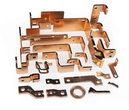
The line had run 1.5 mm SPCC for four years without a single surface complaint. Then the order book changed and the same line started running 2.0 mm C11000 copper for busbars.
By the third coil, the press operator was rejecting every part for surface marking. Nothing on the machine had been touched.
Only the material had changed, and with it a set of assumptions that nobody had written down.
This is what happened next, how the cause was traced, and which settings on an NC straightener feeder have to be rebuilt when copper replaces steel.
The wider picture of where feed error comes from on a coil line is set out in the coil line guide library. The machine range is listed under our machines.
The Copper Job That Looked Like a Steel Job
On paper the change was small. The new part was 0.5 mm thicker than the old one, 300 mm wide instead of 250 mm, and the press tonnage was unchanged.
The tooling was already cut for the busbar profile, so the die did not need to change. The material arrived as 3 tonne coils on the same inside diameter. Every logistics box was ticked.
What changed was the material's mechanical behaviour, and it changed in four directions at once. Copper at 2.0 mm half-hard runs around 250 MPa yield against roughly 180 MPa for the SPCC it replaced.
It is also softer on the surface, more prone to adhering to steel, and roughly three times more thermally conductive. None of those properties appears on a feed setting sheet.
Where Copper Behaves Differently
Four differences drive almost every symptom that followed, and they interact rather than acting alone.
- Copper transfers to steel. Under roll pressure, soft copper micro-welds to a rougher steel roll face and leaves a film behind. The film then marks the next coil, so the defect appears on material that never touched the original cause.
- Springback is lower. Copper needs less penetration to reach the same flatness, so the steel recipe over-rolls it and drives the strip harder into the roll surface than the job requires.
- It stretches earlier. Low yield strength means the same brake torque that held steel at tension will pull copper past its elastic limit and leave a permanent elongation in the strip.
- Its surface is the product. On a busbar, tarnish, embedded iron and roll pickup are not cosmetic. They raise local resistivity and interfere with the downstream welding or plating step.
The fourth point is what made this job different from a normal material change. On an enclosure panel, a light roll mark is a reject only if the customer inspects the visible face.
On a busbar, the surface condition is a functional requirement.
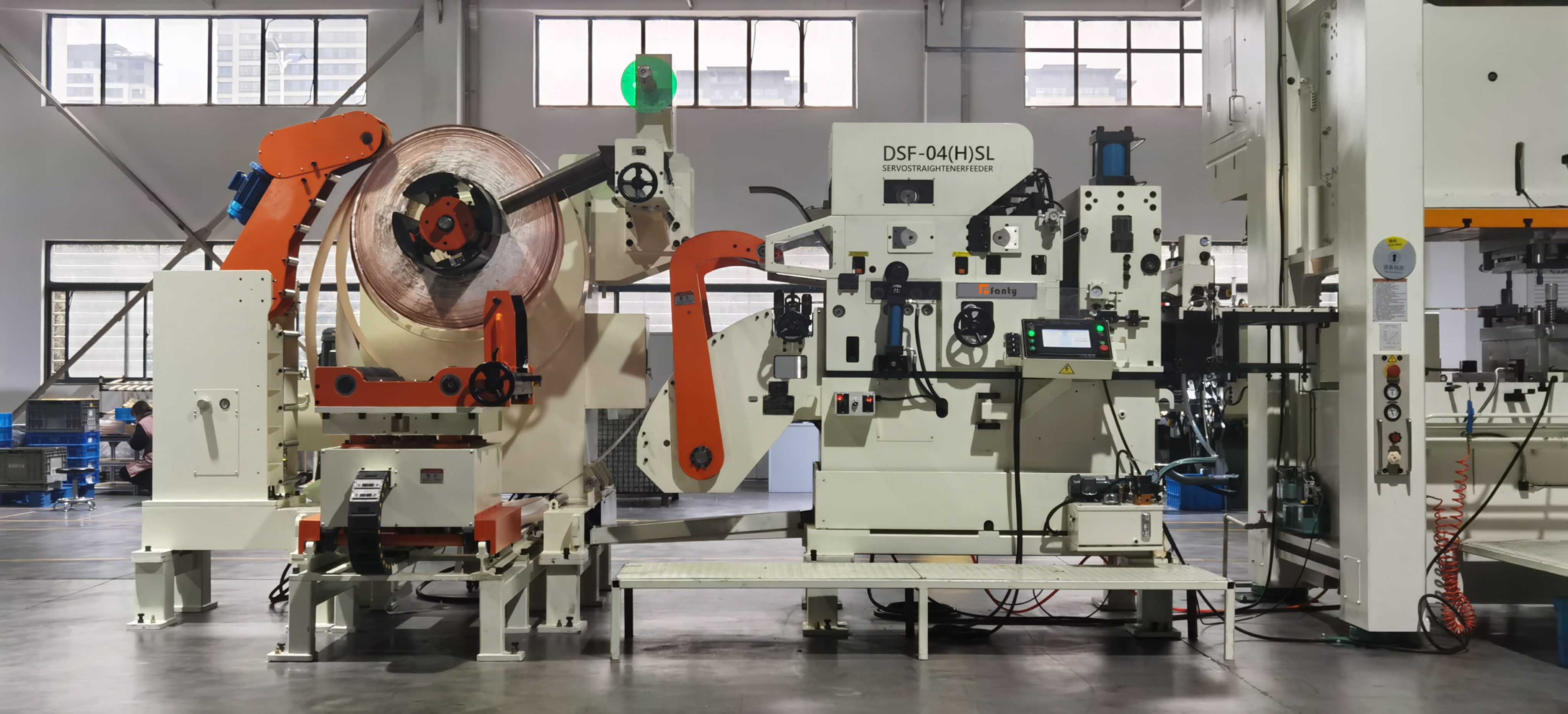
What the Run-Off Data Missed
The machine had been accepted on steel, and its run-off record described steel. Four measurements taken over two shifts showed how far that record had drifted from the new job.
| Behaviour | What it changes on the line | Where it costs you |
|---|---|---|
| Surface adhesion to steel rolls | Roll faces need a finer finish and a shorter cleaning interval | Cleaning went from a fortnightly task to a three-day one, and a missed clean rejects a whole coil rather than a few parts |
| Lower springback | Penetration drops roughly 25 per cent against the steel recipe | Leaving the steel setting in place adds roll pressure, which accelerates pickup and marking without improving flatness |
| Lower yield strength | Brake torque has to come down, or the strip stretches | A 0.2 per cent permanent elongation is invisible on the coil and becomes a length error on every blank |
| Higher thermal conductivity | Blanking heat leaves the shear zone faster, changing burr and sliver behaviour | Slivers stick to copper and travel into the die, so die maintenance rises even though the feeder is running correctly |
The marking was not caused by a worn roll or a bad bearing. It was caused by a steel roll surface at steel penetration, acting on a material that adheres to it.
Measured on the strip, the difference was clear. Feed accuracy had moved from plus or minus 0.05 mm on steel to plus or minus 0.18 mm on copper, and the extra error was traced to lubricant film, not to the servo.
The copper arrived with a heavier mill oil film than the steel supplier had used. On a smooth, hard material that film is harmless.
On copper it acts as a release layer, so the feed rolls lose grip and the strip advances short.
Where Copper Sets Limits on the Machine
A coil line sized for mild steel will run copper, and it will run it well inside a band of thickness and width. Outside that band, no amount of tuning fixes the mismatch.
Roll surface finish becomes the constraint. Standard steel rolls around 0.8 micrometre Ra are too rough for consistent copper work.
Polished or hard-chromed rolls at roughly half that figure are the practical answer, and they are a machine specification, not a setting.
Flattening capability does not scale with softness. Copper arrives with more coil set and crossbow than the steel it replaced, because it is wound at lower tension at the mill.
The strip needs more flattening at entry while tolerating less roll pressure, and those two demands pull against each other.
Roll material matters for contamination. Where the busbar specification limits embedded iron, steel rolls in direct contact are a genuine risk.
A protective film, non-ferrous entry guides, or a dedicated line becomes the honest recommendation.
The lubricant is part of the machine. Copper usually needs a low-residue, weldable lubricant applied thinly. The wrong film either slips under the rolls or leaves a residue that fails the downstream welding test.
How the Setup Changes for Copper
Six adjustments carried this job from a 40 per cent reject rate to under two per cent, and the order they were made in mattered.
Clean the rolls first. The film left by the previous coils had to come off before any setting was judged. Cleaning after a change to copper and again after the first coil is the sequence that works.
Cut penetration by roughly a quarter. Starting from the steel value and working down to the point where flatness just holds is faster than starting from a flatness target.
Halve the back tension, then measure for stretch. Mark a 1 metre length, run it through, and re-measure. Any permanent growth means the brake is still too high.
Reduce the lubricant film, and change the lubricant. A thinner film of a weldable product restored feed accuracy to plus or minus 0.06 mm before the second coil was finished.
Lower feed roll pressure. Copper grips easily. Extra clamping force deforms the strip and marks the edges without improving feed consistency.
Rebuild the recipe table per temper. Annealed copper and half-hard copper need different penetration. One recipe per material family is not enough when the temper changes within the same part number.
Which Steel-Line Numbers You Must Discard
The single biggest source of error on this job was not the machine. It was the assumption that a number measured on steel still described copper.
Feed force and torque tables are material-specific. Catalogue figures are quoted at a nominal strip.
Copper at the same thickness needs less force but offers a different friction pair, so the safe conclusion from a steel table is that the machine has margin, not that the setting will work.
Roll gap charts assume steel springback. A gap derived from steel thickness plus a springback allowance over-rolls copper. Setting gap from thickness alone ignores that the two materials recover differently.
Acceptance data describes one coil. The flatness and accuracy figures recorded at run-off on steel are a baseline for the machine, not a prediction for a new material.
A test cut on the actual copper is the only figure that means anything.
Surface inspection criteria change with the end use. A mark that passes on a painted enclosure panel will fail on a busbar, so the inspection standard has to be rewritten at the same time as the recipe.
When Copper Should Bypass a Coil Line Entirely
There are copper jobs where the correct answer is not a better recipe. It is a different process route.
Thick and wide at the same time. Beyond roughly 3 mm thick and 400 mm wide, flattening a copper coil to a tight flatness spec calls for a leveler with larger rolls and a dedicated drive.
That is a machine decision rather than a recipe decision. A line sized around a steel job does not become a copper line because the settings were retuned.
When the surface specification forbids contact. Some busbar and vacuum-grade copper specifications limit surface contamination severely.
If a roll-type line cannot meet that limit with the roll materials available, the strip has to be supplied as cut lengths or processed on a contact-free route.
When the volume does not justify it. A few hundred copper parts a month is a shear-and-blank job.
Setting up a coil line, a recipe, a lubricant change and a cleaning regime for that volume costs more than buying copper in cut lengths.
When the temper varies between deliveries. If half-hard and annealed copper arrive on the same part number, the recipe chases the material and the process never stabilises.
That is a purchasing problem, and it is cheaper to fix at the purchase order than on the line.
FANTY builds around 200 active coil line installations, and the copper work follows a consistent pattern. The machine itself rarely has to change.
The recipe, the lubricant, the roll surface and the inspection standard always do.
Questions that come up when a steel line is asked to run copper.
How much less penetration does copper need than 1.5 mm steel?
Around 20 to 30 per cent less on comparable thickness, because springback is lower. Start about a quarter below the steel value and work down until flatness just holds.
Does a 3 mm copper coil still suit a roll-fed line?
Typically beyond 3 mm at 400 mm width, or whenever the flatness specification tightens below what the existing roll diameter can deliver.
Do copper jobs wear feed rolls faster than steel?
They fail differently rather than faster. Abrasion drops, but copper pickup rises, and the cleaning interval can fall from two weeks to three days.
Can iron from steel rolls contaminate a copper busbar?
It can. Embedded iron raises local resistivity and interferes with welding, so specifications that limit contamination need non-ferrous guides or a protective film.
How much back tension can a 2.0 mm copper strip take?
Permanent elongation appears around 0.1 to 0.2 per cent strain. On a 2.0 mm by 300 mm strip that is roughly 1 to 1.5 kN, so keep the brake well under it.
Where to go next
Copper changes the recipe, the lubricant and the inspection standard before it changes the machine. The error budget that governs how much of this a coil line can absorb is worked through in the feed accuracy guide.
the coil line guide library