How Does Pilot Release Affect NC Servo Feeder Accuracy?
- Share
- publisher
- FANTY
- Issue Time
- Sep 10,2026
Summary
Pilot release timing is the least visible setting on an NC servo feeder and one of the most consequential. This article explains the crank angle window, how early and late release differ in the damage they cause, and the controller procedure for setting both angles.

Pilot release timing is the least visible setting on an NC servo feeder and one of the most consequential. It determines the moment the pilot pins are allowed to enter the strip, relative to the moment the feed rolls let go. Get it right and the die pilots correct any residual position error on every stroke. Get it wrong and the pins either fight the feeder or arrive too late to do their job — and both failures look like a feed accuracy problem rather than a timing problem.
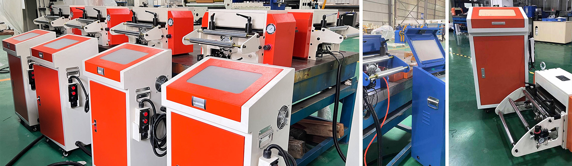
What pilot release does inside the cycle
A progressive die locates the strip with pilot pins that enter pilot holes before the working stations engage. Those pins can only do their job if the strip is free to move — which means the feed rolls must have released their grip, and the strip must not be held by the feeder's anti-backup device.
Pilot release is the signal that tells the feeder to let go. On an NC servo feeder it is normally triggered from the press crank angle, either through a rotary cam switch or a programmable output, and it opens the feed rolls and releases the anti-backup for a defined window. The window has to open before the pilot pins reach the strip and close after they have withdrawn.
This is why pilot release sits at the intersection of two machines. The feeder controls its own rolls; the press controls the crank position. The timing that matters is the relationship between them, and it shifts whenever either machine's settings change.
The crank angle window, in degrees not milliseconds
Setting pilot release in milliseconds is a mistake, because the window has to track the crank, not the clock. Press speed changes, but the crank angle at which the pilots enter does not. So the release window should always be expressed in degrees of crankshaft rotation.
On a typical progressive die, the pilots enter somewhere between 150 and 180 degrees after top dead centre, depending on die design and pilot length. The feeder should release roughly 10 to 20 degrees before that and re-engage 10 to 15 degrees after the pilots have cleared — which usually puts the close signal somewhere around 300 to 330 degrees.
Converted to time, that window is short. At 250 SPM a full revolution takes 240 ms, so 15 degrees is 10 ms. At 400 SPM the same 15 degrees is 6.25 ms. The mechanical release mechanism has to open and close within that budget, which is why high-speed feeders use fast-acting pneumatic or servo-driven release rather than a slow solenoid valve.
| Observed problem | Likely timing issue | Direction of correction |
|---|---|---|
| Pilot pins shear or mark the hole edge | Release too late — rolls still gripping when pins enter | Advance the release signal 5-10 degrees |
| Strip shifts after the pilots withdraw | Release held too long — strip free with no location | Close the rolls earlier, around 310-320 degrees |
| Hole position drifts progressively over a run | Marginal release — intermittent pin interference | Widen the window and re-verify |
| Feed pitch inconsistent only at high speed | Release valve cannot keep up with the window | Upgrade to fast-release hardware |
| Strip marks only on one side of the hole | Pilot entry with partial grip, strip skewed | Check anti-backup release, then advance timing |
| Die damage on the first stroke after a stop | Timing lost on restart or manual jog | Verify the signal source is crank-locked, not cycle-counted |
Early release versus late release
Both errors damage tooling, but they damage it differently and the evidence is distinguishable.
Late release is the more common and more destructive of the two. The feed rolls are still closed when the pilot pins descend, so the pins have to drag the strip into position against the feeder's grip. The visible result is elongated or torn pilot holes and, over time, worn pilot pins and a cracked die block. Operators often describe it as the die "pulling" the strip. In practice the strip position is fine and the timing is the fault.
Early release is gentler but harder to diagnose. If the rolls open well before the pilots arrive, the strip sits unlocated for a few milliseconds. On a well-supported die this is harmless; on a die with long unsupported spans, or on thin strip, the strip can shift slightly under its own tension. The result is a position error that appears intermittently and does not correlate with feed length or speed.
A useful test is to measure the pilot hole condition over a run of several thousand strokes. Clean, round holes mean the timing is close. Slightly elongated holes in the feed direction mean the release is late. Randomly offset holes with no elongation mean the strip is free too long.
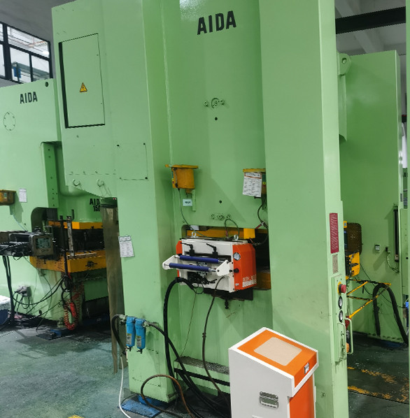
Setting it on the controller
Most NC servo feeder controllers expose pilot release as two crank-angle setpoints: a release-on angle and a release-off angle. The procedure is the same across platforms.
- Confirm the crank angle signal source. It must come from an encoder or rotary cam on the press, not from a counter in the feeder controller.
- Determine the actual pilot entry angle from the die drawing or by inching the press with the strip marked.
- Set release-on 15 degrees before pilot entry as a starting point, then close the window in 5-degree steps.
- Run at production speed and inspect pilot holes. Repeat until holes are clean and round.
- Record the final angles on the die setup sheet. Every die change should start from a documented pair, not from scratch.
One setting that catches people out: the anti-backup or strip clamp release. If the feeder opens the feed rolls but leaves the anti-backup engaged, the strip is still restrained and the pilots will fight it exactly as though the release were late. Verify both signals open together, using the controller's diagnostic display if it has one.
On an NC Straightener Feeder, where the straightening roll stack sits between the feed rolls and the die, the strip is held at two points rather than one. That changes the release requirement: the straightener rolls must also relax their grip, or the pilots will pull the strip against the roll pressure instead of against the feed rolls. Machines that share a common frame between feeder and straightener usually handle this with a single coordinated release output, but it is worth confirming on the wiring diagram rather than assuming it.
Where feed accuracy is quoted at ±0.05 mm, that figure assumes the strip is properly located by the die on each stroke — the feeder positions the strip, and the pilots finish the job. If pilot release timing is wrong, the feeder is being asked to hold a tolerance that the die was designed to help with, and no amount of servo tuning will recover it.
Symptoms that point here, not at the servo
Before tuning servo gains, rule out timing. The giveaway patterns are holes that are elongated rather than offset, die damage that appears after a speed change or a die change rather than gradually, and feed position error that is within specification when the press runs slowly and out of specification at full rate.
The last one is the clearest signal. Servo tuning errors usually show up across the whole speed range. A fault that appears only at speed, with good performance at low rate, is far more often a release window that the hardware cannot execute fast enough — a valve that is too slow, a signal that is delayed, or a window set in milliseconds that no longer fits the cycle.
FANTY builds feeder and straightener packages to CE requirements and ships them to more than 60 countries, so the release timing conventions that work across different press platforms are well documented rather than guessed at. If a line has a persistent timing fault, the fastest route is usually to bring the die setup sheet and the press crank diagram together and check the two against each other.
Should pilot release be set in degrees or milliseconds?
Degrees. The pilot pins enter at a fixed crank angle regardless of press speed, so the release window must be crank-referenced. A window set in milliseconds will drift out of position the moment line speed changes.
What happens if pilot release is never enabled?
The feed rolls stay closed while the pilots descend, so the pins drag the strip into position. Pilot holes elongate, pilot pins wear quickly, and in severe cases the die block cracks. It is one of the more expensive ways to save a setup step.
Does pilot release timing need to change with strip thickness?
Not usually, but thicker or harder strip needs a slightly wider window because the pins require more force to locate the strip. Add a few degrees on each side rather than shifting the window.
Why does the problem only appear at high speed?
Because the mechanical release has a fixed actuation time. At low speed the window is generous in absolute terms; at high speed the same window shrinks to a few milliseconds and a slow valve can no longer complete the motion in time.
Pilot holes tearing on every run?
Send your die drawing detail, press crank angle and line speed. FANTY's engineers will work out the correct release window and tell you whether your existing release hardware can execute it.
Get Your Timing Checked