How Does Strip Get Guided Into an NC Servo Feeder?
- Share
- publisher
- David Park - Senior Stamping Engineer, FANTY Machinery
- Issue Time
- Oct 13,2026
Summary
Entry guides get blamed for feed faults that start further up the line. A downstream-to-upstream setup routine for an NC servo feeder: pass line, exit guide squareness, roll gap, entry gap and a full-coil verification, with the three cases where no guide setting can help and the five numbers worth recording on the setup sheet.
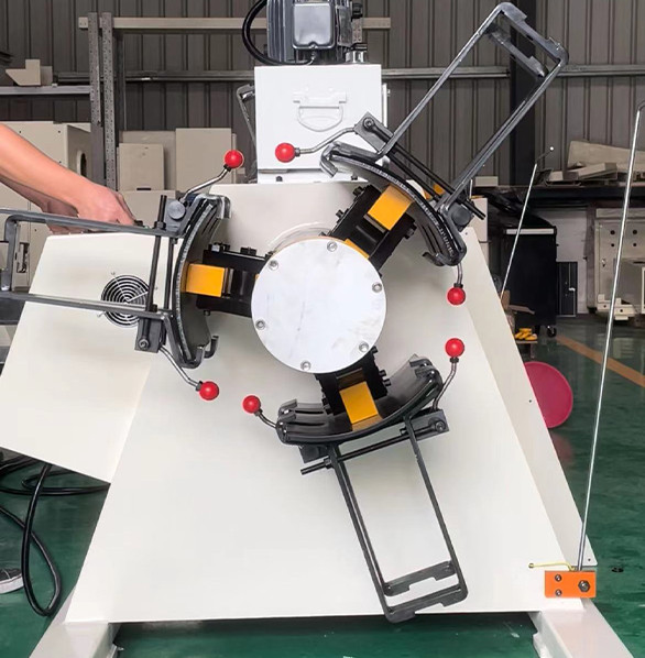
Strip enters a feeder through two guides and a pair of pinch rolls. That is the whole mechanism, and it is where a large share of "feed faults" actually begin.
Edge damage, lateral drift and short feeds get reported as control problems. Most of them trace back to a guide that was never squared to the roll axis in the first place.
Here is a six-part setup routine for the entry side of an NC servo feeder, in the order a service engineer would actually work through it.

Set the Line Before You Touch the Guides
Guides are the last thing to adjust, not the first. If the pass line height or the roll axis is wrong, no guide setting will compensate for it.
Establish the pass line. On most presses the pass line is fixed by the die and the bolster, and everything upstream is set to match it. Confirm it from the die drawing rather than from the machine that ran last.
Confirm the roll axis is parallel to the pass line. A feeder sitting 0.5 mm out of parallel across 250 mm of strip will steer the material continuously. It looks like a guide fault and is not one.
Level the feeder feet before shimming anything else. Twist in the base shows up as a strip that tracks differently on the left and right of the coil, which operators usually blame on camber.
Do these three checks with a dial indicator and a straight edge. They take half an hour and they remove most of the reasons a guide would need to be adjusted at all.
Five Steps From Pass Line to Die Entry
Work downstream to upstream. Setting the die entry first means every earlier adjustment is measured against the right reference.
Step 1: centre the strip on the die. Set the strip on the die centreline with the die open, using the pilot or the first station as the reference. Do not centre it on the machine frame.
Step 2: square the exit guide to the roll axis. The exit guide sets the strip direction into the die. A 0.2 mm error here becomes visible as lateral drift over a 180 mm feed.
Step 3: set the roll gap. For 1.5 mm strip, a gap 0.05 to 0.10 mm under nominal gives grip without crushing the edge.
Step 4: set the entry guide gap. Allow 0.5 to 1.0 mm total clearance over strip width, so a 250 mm strip runs in a 251 mm gap. Tight guides mark edges; loose guides let the strip wander.
Step 5: verify with a full-length run. Feed a full coil and watch the strip edge against the guide at the start, middle and core. Movement of more than 0.5 mm needs a re-check of step 2.
| Guide Setting | Wrong Setting Looks Like | Correct Reference | Where It Costs You |
|---|---|---|---|
| Pass line height | Strip bowing up or down at the die | Die drawing and bolster height | Costs nothing to check, but forces the guides to fight a geometry error permanently |
| Exit guide squareness | Lateral drift that grows with feed length | Roll axis, measured with a dial indicator | Needs an indicator and patience; the payoff is that entry guide tuning becomes almost unnecessary |
| Roll gap | Edge crush or slip | 0.05–0.10 mm under nominal thickness | Too tight marks the edge, too loose loses grip; there is no setting that fixes both |
| Entry guide gap | Edge marking or wandering strip | Strip width plus 0.5–1.0 mm total | A tight guide protects tracking but marks soft or coated edges |
Note the pattern in the last column. Every guide setting is a trade, and the correct value is the one that pushes the failure mode onto something the part can tolerate.
The Checks That Catch a Bad Setup Early
You can confirm the entry side in ten minutes at the start of a shift, and it is worth doing after every die change.
- Mark the strip edge at the entry guide and check the mark after fifty strokes. Movement over 0.5 mm means the guide or the roll axis has moved.
- Feel the strip edge for a burr or a polished line. A guide that is too tight leaves a bright rub mark within a few hundred strokes.
- Compare feed length at the outside wrap and at the core. A difference over 0.1 mm points to grip, not to guides, and the two get confused constantly.
Two of those three checks need no instruments. That matters on a shop floor where the gauge set lives in the tool room and the die change happens at 6 a.m.
Limits of Guide Adjustment
Guides correct position. They cannot correct a material or a process problem, and three cases are worth recognising before an afternoon disappears into guide tuning.
Coil camber. A coil with built-in camber will track to one side no matter how square the guides are. Guides only hold it until the force from the camber overcomes them, and then it moves again.
Coil set or a distorted eye. If the coil does not pay out flat, the strip arrives at the guide with a lateral velocity already in it. The guide absorbs the motion and marks the edge doing it.
Very narrow or very thin strip. Below roughly 40 mm wide or 0.4 mm thick, guide contact force starts to buckle the strip instead of steering it. A guide cannot push on a strip that bends away from it.
In all three cases the honest answer is to fix the coil or the payoff rather than the guide. Recognising that early is worth more than any amount of adjustment skill.
How Guide Position Drifts Between Shifts
Most guide faults are not caused by a bad setup. They are caused by a good setup that slowly changed and nobody noticed.
Loose lock screws. A guide held by two screws and adjusted weekly will creep. Check torque at every die change rather than every quarter.
Guide faces wearing into a taper. The entry edge of a guide wears faster than the exit edge, so the effective gap widens over months even though the setting never moved.
Different operators, different feel. If the guide gap is set by feel rather than by gauge, the setting varies by shift. That variation shows up as a quality difference between shifts, not as a fault.
Write the gap value and the reference method on the setup sheet. A number that can be checked in thirty seconds is what keeps a setup stable across three shifts and two operators.
| Check | Frequency | What It Catches | Where It Costs You |
|---|---|---|---|
| Guide lock screw torque | Every die change | Slow creep of the entry guide | A minute of work per change; skipped, it costs a shift of chasing drift |
| Guide face condition | Monthly | Taper wear that widens the gap | Replacement faces are consumables, and replacing them early costs more than the wear does |
| Strip edge mark check | Every shift start | Over-tight guides before they damage a coil | Takes ten minutes and requires the operator to actually look at the edge |
| Feed length at outside and core | Every coil change | Grip loss disguised as a guide fault | Adds a step to the changeover that production will resist until it prevents one bad coil |
What to Record on the Setup Sheet
A setup sheet is only useful if the numbers on it can be checked without a gauge set. Keep it to five entries and it will be used.
Strip width and guide gap. The nominal width and the actual gap, so the next operator can confirm the gap rather than re-derive it.
Pass line height. Measured to a fixed point on the machine, not to the floor, because the floor is not a datum.
Roll gap and roll pressure. Recorded for the material actually running, since the next job may be a different thickness on the same die.
Feed length and rate. With the press speed at which it was proven, because feed behaviour changes with acceleration and acceleration changes with rate.
Any deviation accepted. If the guide had to run 0.3 mm wide to stop edge marking, write it down. Otherwise the next shift will tighten it back and recreate the problem.
FANTY's units are shipped with a CE-marked control package and a setup record.
Customers in more than 60 countries run them across three-shift patterns where exactly this discipline decides whether the setup survives the week.
Model sizes and guide options are listed on the feeder range page.
How much guide clearance does 1.5 mm strip need?
Allow 0.5 to 1.0 mm of total clearance over strip width. On a 250 mm strip that means a 251 mm gap, and on coated stock it is worth running at the wide end of that range.
Does 1 mm of guide offset matter on a 180 mm feed?
Yes. A 1 mm lateral offset at the entry guide produces roughly 0.6 mm of drift at the die over a 180 mm feed, which is enough to close a pilot clearance.
Should guides be re-squared every 500 or 5,000 strokes?
Neither. Re-square after any die change, any foundation work and any report of drift. On a stable line, 5,000 strokes without a check is normal and acceptable.
Where to go next
Guide position is one line in the feed accuracy budget, next to loop control, back tension and pilot release timing. The full budget from the payoff to the die is set out in the same cluster.