How Does a 1,300 mm Feeder Handle a 400 mm Strip?
- Share
- publisher
- David Park - Senior Stamping Engineer, FANTY Machinery
- Issue Time
- Oct 26,2026
Summary
A line that had run 1,200 mm coil for two years moved to a 400 mm strip and started scrapping 9% of parts. This field case walks through the diagnosis: 0.09 mm of roll deflection at mid-span, 3 mm of strip walk over 200 strokes, and pilot release timing set for a much wider strip. It records what each fix actually moved, what made the marking worse, and the width ratio below which a wide feeder cannot be saved.
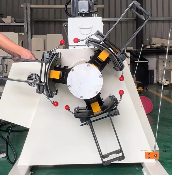
A customer called in March with a line that had run perfectly for two years and then started scrapping parts. The machine had not changed. The work had.
They had moved from 1,200 mm blanks to a 400 mm wide strip on the same 1,300 mm NC servo feeder. Everything about the setup looked right on paper.
The Job That Broke the Line
The press ran a progressive die at 180 SPM on 1.2 mm galvanised strip, 400 mm wide. Feed length was 310 mm with a tolerance of ±0.15 mm on the finished part.
For the first eighteen months the line ran 1,200 mm wide coil on the same feeder. Same die, same press, same operator, and no complaints.
The new job arrived in February: a smaller part, a narrower strip, and a customer who wanted 60,000 pieces a month.
Within two weeks the scrap rate went from 1.2% to 9%. The parts were short by 0.2 mm to 0.4 mm, intermittently, with no obvious pattern across a shift.
Nothing in the machine had worn out. The feeder was doing exactly what it was set to do, for a strip width it had never been set for.
The First Two Hours on Site
I spent the first hour watching the strip rather than the screen. The strip walked 3 mm to the left over about 200 strokes, then the operator nudged the guide and it started again.
The second hour went to measurement. Feed length was good on the first twenty strokes and drifted once the line reached temperature.
Then we checked the roll gap with a strip sample and a shim set. The gap at the strip edges was 0.12 mm wider than at the centre of the roll face.
That single reading explained most of the symptom. A narrow strip sits in the middle of a wide roll pair, exactly where roll deflection is largest under load.
The same reading explained the marking. Less contact area means higher pressure per square millimetre, and galvanised coating shows that immediately.
Feed length looked stable on the screen because the encoder counts roll rotation, not strip movement. Slip between roll and strip is invisible to it.

Three Causes, Only One of Them Mechanical
Narrow strip in a wide feeder produces a small set of failures, and they arrive together. Separating them is most of the diagnostic work.
| Cause | How it shows on the floor | Where it costs you |
|---|---|---|
| Roll deflection at the centre | Short feeds that grow with line speed | 0.1 mm of gap error becomes 0.3 mm of length error |
| No edge guidance | Strip walks a few millimetres over a few hundred strokes | Pilot damage and die repair, not just scrap |
| Pilot release timing set for wide strip | Marks at the pilot holes, occasional bent pilot | Tooling life measured in weeks rather than months |
Deflection was the mechanical one, and the easiest to prove. Two dial gauges under the lower roll, loaded and unloaded, showed 0.09 mm of movement at mid-span.
Guidance was the second. The line had side guides set for 1,200 mm coil, leaving 450 mm of clearance on each side of a 400 mm strip.
Timing was the third, and the least obvious. Pilot release had been set for a 1,200 mm strip that needed a longer dwell to settle.
Each cause produces a different signature, which is why changing three settings at once is a bad idea. You lose the ability to tell which one worked.
We changed them one at a time, with a 200-piece run between each. That discipline cost half a day and saved a week of guessing.
What Fixed It, and What Did Not
The fix took a day and a half, and only one of the four actions was expensive. The order matters, because two of them are free.
- Re-shim the gap on the strip, not the roll face. Set it with the actual 400 mm sample in place, then verify at both edges.
- Add guide rollers within 30 mm of the strip edge. A pair of vertical rollers costs little and removes the walk entirely.
- Shorten pilot release dwell by 12 degrees. Enough for the strip to settle, short enough that pilots do not push it sideways.
- Move the measuring point to the die. Measure the part, not the feed length on the screen, and the argument ends.
The gap change alone took the length error from 0.4 mm to 0.12 mm. The guide rollers removed the walk but did nothing for length, which surprised the operator.
Pilot release timing fixed the marks at the holes. It was the cheapest of the four changes and the last one anybody suspected.
What did not work was increasing hold-down pressure. That flattened the strip slightly and made the marking worse, because the force went through the same narrow contact band.
We also tried slowing the line to 120 SPM. Length error improved by 0.05 mm and the walk stayed exactly as it was, which confirmed the two faults were independent.
That test was worth running. It cost twenty minutes and told us the deflection and the guidance needed separate fixes, not a compromise setting.
| Change | Measured effect | What it did not fix |
|---|---|---|
| Gap re-shimmed on strip | Length error 0.4 mm to 0.12 mm | Strip walk |
| Guide rollers added | Walk 3 mm to 0.2 mm over 500 strokes | Length error |
| Pilot release shortened | Edge marks eliminated | Feed accuracy at high speed |
| Hold-down pressure raised | Made marking worse | Nothing useful |
The Two-Week Invoice, Line by Line
Scrap gets the attention, and it is rarely the largest number. On this job the die damage cost more than the wasted strip.
At 40,000 pieces a month, moving from 1.2% to 9% scrap meant about 3,100 extra rejected parts. At roughly $1.20 of material and press time each, that is $3,700 a month.
Two pilot punches were replaced and one die section was re-ground after the strip walk bent a pilot. That invoice came to $2,800, once.
Add the engineer visit, the lost production during two days of trials and the expedited shipping on the customer's order, and the episode cleared $9,000.
The four fixes cost under $600 in parts. The lesson is not that the fixes were cheap; it is that the diagnosis was the expensive part.
Where a Wide Feeder Cannot Be Saved
Re-shimming and guiding buy you a working job, not a good one. There is a floor below which a wide feeder stops being the right machine for narrow strip.
The ratio matters more than the absolute width. Once strip is under about 30% of the roll face, deflection and contact pressure dominate the accuracy budget.
On this line, 400 mm against 1,300 mm is 31%, which sits right at the edge. A 250 mm strip on the same machine would not have been recoverable.
Speed compounds it. At 180 SPM the strip has 0.33 seconds per cycle to settle; the same setup at 300 SPM would need a different machine, not a different setting.
Thin material compounds it again. Galvanised 1.2 mm tolerates a little contact pressure; 0.5 mm aluminium shows every mark and deflects under the rollers.
And none of this touches the real limit: a feeder cannot fix strip that arrives with camber. If the coil was slit badly, the walk will return no matter how many guide rollers you fit.
What I Would Specify Next Time
Three questions would have prevented the whole episode, and all three belong in the enquiry rather than the commissioning report.
Ask what strip width range the feeder is expected to cover, and what percentage of the roll face the narrowest job represents. A supplier who cannot answer that is quoting a catalogue.
Ask how the gap is set and verified at the strip edges. A machine that only offers a single gap dial at the centre is a machine for full-width work.
Ask whether guide rollers are included or optional. On a line that will ever run narrow strip, they are not an accessory.
Ask for the deflection figure at mid-span under rated load. It is a single number, and any serious builder knows it.
Our own R&D team sizes roll deflection against the narrowest job on the enquiry sheet, not against the widest. That habit came from jobs like this one, and from 200-plus lines running in 60 countries.
The wider error budget, from coil to die, is worked through in the coil line guide library.
Can a 1,300 mm feeder hold ±0.05 mm on a 400 mm strip?
Not without re-shimming and edge guidance. Expect ±0.12 mm after the fixes, and ±0.05 mm only on a feeder sized closer to the strip width.
How much gap error does 0.09 mm of roll deflection produce?
About 0.09 mm of roll deflection on this machine under load, which produced 0.4 mm of length error at 310 mm feed length.
Can a 250 mm strip run on a 1,300 mm feeder?
Below 30% of the roll face. At 250 mm on a 1,300 mm machine the deflection cannot be shimmed out at production speed.
Where to go next
This case sits inside a larger error budget, where roll deflection is one line among five. The full breakdown from coil to die is in our coil line knowledge base.
The Coil Line Guide Library