How Does an NC Servo Feeder Achieve ±0.05mm Feeding Accuracy for High-Speed Stamping?
- Share
- publisher
- FANTY Industries
- Issue Time
- Jul 20,2026
Summary
Discover how NC servo feeder feeding accuracy of ±0.05mm transforms high-speed stamping production. Comprehensive guide covering technology, components, installation.
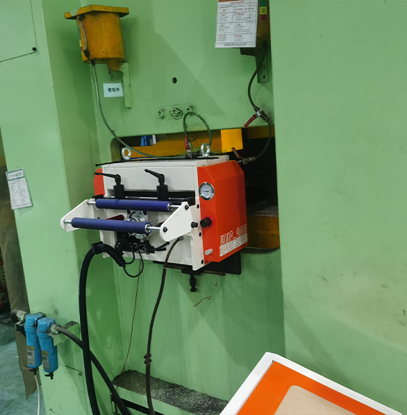
Feeding accuracy is the single most critical performance parameter in high-speed stamping. An NC servo feeder achieving ±0.05 mm repeatable accuracy transforms production quality, reduces scrap, and extends die life.
This guide examines the technology, components, and engineering that make sub-0.1 mm feeding possible at speeds exceeding 200 strokes per minute, helping you understand what to look for when investing in precision feeding equipment.
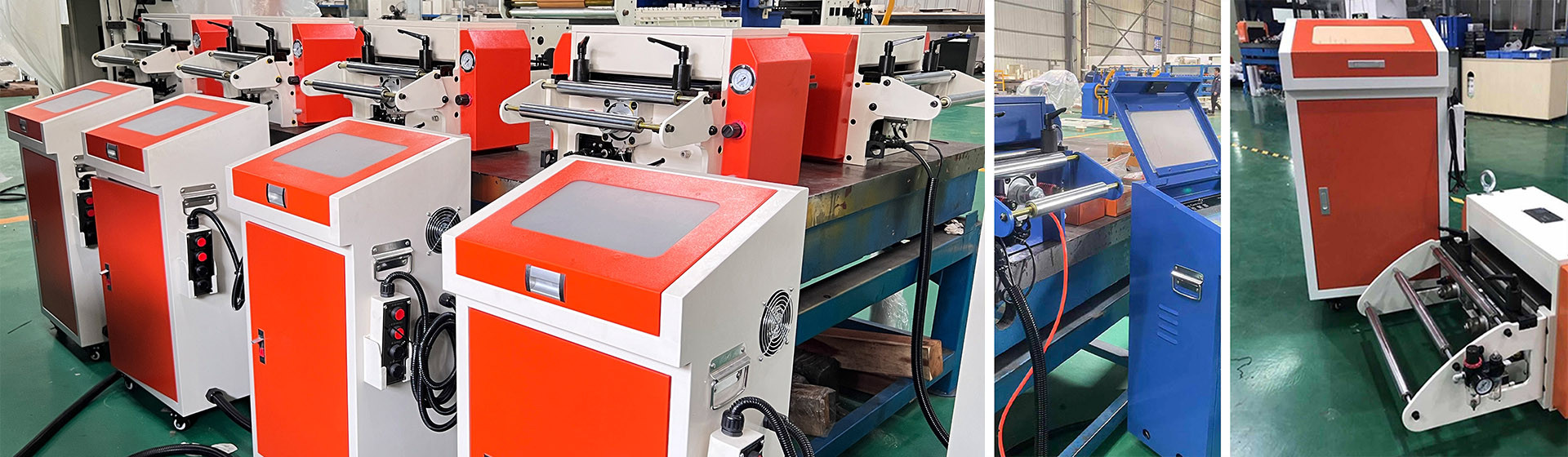
The Core Technology Behind ±0.05 mm Accuracy
Unlike open-loop systems that assume the motor has reached the commanded position, an NC servo feeder uses a rotary encoder mounted directly on the servo motor shaft. The encoder sends real-time position feedback to the servo drive hundreds of times per second.
The servo motor must be sized correctly for the application. An undersized motor cannot maintain accurate positioning under heavy load or rapid acceleration.
FANTY's NC servo feeders use Yaskawa servo motors rated with sufficient torque margin (typically 150-200% of peak load) to handle peak loads without losing position.
The acceleration and deceleration profiles are programmable through the touchscreen HMI, allowing operators to optimize the feed motion for each specific material and die combination.
A gentler acceleration profile improves accuracy for thin or delicate materials, while aggressive profiles maximize throughput for robust stamping applications.
Encoder Resolution and Its Impact on Accuracy
The encoder resolution directly determines the theoretical positioning precision of the feeder. A standard 2,500 pulse-per-revolution (PPR) encoder combined with electronic gearing provides approximately 0.01 mm per pulse resolution — adequate for most general stamping applications.
High-precision feeders use 10,000 PPR encoders that achieve 0.002 mm per pulse resolution. However, the actual achievable accuracy also depends on mechanical factors such as roller concentricity, bearing quality, and frame rigidity.
A high-resolution encoder on a mechanically sloppy frame will not deliver high accuracy.
Feeder Accuracy Comparison
| Feeder Type | Typical Accuracy | Encoder | Control Method | Max Speed |
|---|---|---|---|---|
| NC Servo Feeder (Premium) | ±0.03 - 0.05 mm | 10,000 PPR rotary | Closed-loop PID | 200+ SPM |
| NC Servo Feeder (Standard) | ±0.05 - 0.10 mm | 2,500 PPR rotary | Closed-loop PID | 150+ SPM |
| Mechanical Feeder | ±0.20 - 0.50 mm | None | Cam / open-loop | 80-120 SPM |
| Pneumatic / Air Feeder | ±0.30 - 1.00 mm | None | Open-loop | 60-100 SPM |
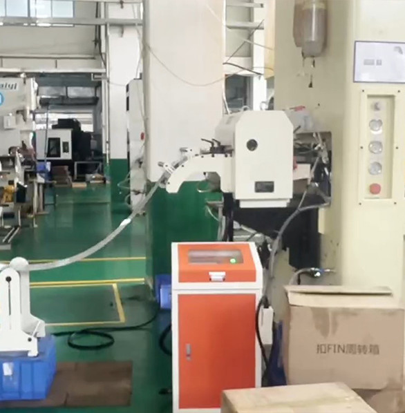
Key Mechanical Components That Maintain Accuracy
Three critical mechanical components work together to maintain ±0.05 mm accuracy over millions of cycles. First, the feed rollers must be precision-ground with chrome-plated surfaces at HRC 58-62 hardness to minimize slippage and maintain consistent material grip. Second, the roller pressure system, typically pneumatic or servo-driven, must maintain consistent force across the material width, compensating for thickness variations within ±0.1 mm. Third, anti-backlash gearing with under 3 arc-minutes of backlash ensures that motor rotation translates directly to roller movement without mechanical play or lost motion.
Common Factors That Degrade Accuracy
- Roller wear: After 1-2 million cycles, feed roller surfaces develop microscopic wear patterns that reduce grip and introduce consistent positioning errors
- Material slippage: Oily, coated, or polished materials can slip between rollers if pneumatic pressure is not adjusted for the specific material
- Encoder drift: Encoder coupling alignment can shift over time due to vibration, temperature changes, or coupling wear, causing incorrect position readings
- Mechanical backlash: Gearboxes and shaft couplings develop wear over time, introducing mechanical play that reduces positioning precision
Frequently Asked Questions
How often should I recalibrate my NC servo feeder?
FANTY recommends a full accuracy verification every 6 months or 500,000 cycles. Daily: run a simple test feed and measure with a caliper. Weekly: verify encoder coupling alignment. Monthly: check roller surface condition and replace if worn.
Does feeding speed affect accuracy?
Yes. At very high speeds above 180 SPM, acceleration and deceleration forces can cause slight overshoot or undershoot of the target position. FANTY's feeders include programmable acceleration profiles that maintain ±0.05 mm accuracy up to 200 SPM for most applications.
Can the same feeder maintain accuracy with different material types?
Yes. Modern NC servo feeders store multiple job profiles, each with optimized acceleration, roller pressure, and feed length settings for specific materials. Switching between 1.2 mm aluminum and 2.0 mm steel is as simple as selecting the saved profile.
Related reading
- which part limits feeding accuracy
- what feeding accuracy to expect
- how to hold feed accuracy on a coil line
Part of the the coil line guide library — the full library of coil handling, straightening and feeding guides from FANTY.
Need guaranteed ±0.05 mm feeding accuracy? Contact FANTY's feeding experts for a tailored recommendation.