How to Commission a 3-in-1 Straightener Feeder on Site
- Share
- publisher
- David Park - Senior Stamping Engineer, FANTY Machinery
- Issue Time
- Nov 2,2026
Summary
A five-day commissioning sequence for a 3-in-1 line, in the order we run it on site, with the pass thresholds for each step. Covers foundation and supply checks, level and pass-line alignment, interlock proof tests, first-strip threading, feed length and pilot timing, and a speed ramp table that names how each test can flatter you.
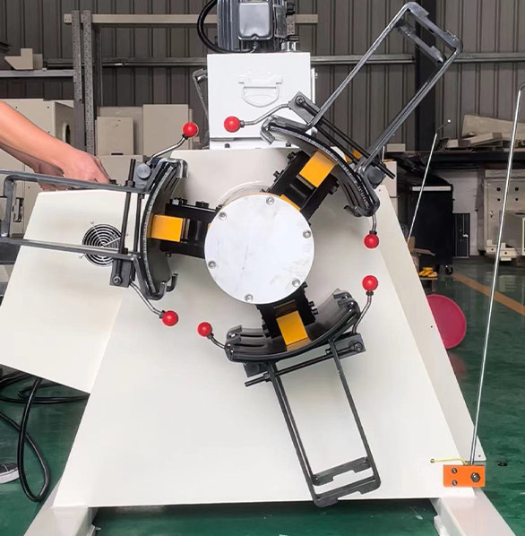
The machine arrived on a Thursday, sat under a tarpaulin for two days while the foundation cured, and was running production the following Wednesday.
Five working days is a realistic commissioning window for a 3-in-1 line in the 800 mm to 1,300 mm class, and the sequence matters more than the speed.
What follows is the order we use on site, the numbers that decide whether each step passes, and the four checks that a rushed start-up tends to skip.
Before the Machine Lands
Half the commissioning problems we see are site problems that were decided before the machine was shipped.
Foundation. A 5-tonne capacity line puts roughly 60 kN on the floor through four feet during a full-coil acceleration. A 150 mm reinforced slab is the usual minimum; a mezzanine is not.
Power. Confirm the supply against the nameplate before the cable is pulled, not after. A 15 kW line on a 400 V supply draws about 30 A per phase at full load, and the breaker has to be sized for the drive's inrush.
Air. Most 3-in-1 machines need 6 bar at 300 litres per minute for the mandrel expansion and the brake release. A 4 bar shop supply will run the line and fail the expansion.
Access. The coil loading side needs a crane or a coil car with a clear approach. A machine that cannot be loaded is a machine that cannot be commissioned.
Day One: Level, Anchor, Align
Level and alignment set the ceiling on everything that follows. A line that is out of level by 0.2 mm per metre will produce a flatness complaint that no roll setting can remove.
Level the base in both directions to 0.05 mm per metre, using a precision level on the machined pads rather than on the guards.
Anchor, then re-check. Grouting and torqueing move a frame by a few hundredths of a millimetre, and that is enough to matter.
Align the pass line between the uncoiler mandrel, the straightening head and the feed rolls to within 0.1 mm over the full line length. Check it with a wire and a dial gauge, not with a straightedge.
Square the line to the press. The feed rolls must present strip to the die at 90 degrees, and a 0.5 mm offset over 2 m shows up as a camber complaint on the first coil.
Day Two: Power, Air and the Safety Circuit
Day two is electrical, and it is the day that decides whether the machine can be started at all.
Check rotation direction on the uncoiler motor before coupling anything. A reversed mandrel motor will expand a coil the wrong way and damage the wraps.
Test every interlock individually rather than as a group. Light curtain, guard switch, emergency stop and the die-height limit each need a separate proof that the drive stops when it should.
Set the air regulator to the pressure on the drawing and watch the gauge during a mandrel expansion. A 0.5 bar drop across the cycle means the supply line is undersized.
Record the settings. Every number you set on day two is a number somebody will need in year three.

Day Three: First Strip Through the Head
Thread the first coil at low speed, in manual, with the die open and the press in inch mode.
Set the straightening roll gap to strip thickness minus 0.1 mm as a starting point, then adjust for flatness rather than for a number on a dial.
Check the strip against a straightedge on the exit side. A 1 m sample should sit within 0.5 mm of straight for general stamping work, and within 0.2 mm for a visible panel.
Look at the strip surface after the head, not before. Roll marks that appear after the head are a penetration or a roll-condition problem, and both are cheaper to fix now than after 20,000 strokes.
Set the loop. A loop that is too short pulls the strip tight against the uncoiler and shows up as length error at speed; too long, and the strip drags on the floor.
Day Four: Feed Length and Pilot Timing
Feed length is set against a measured part, not against the controller display.
Run 20 strokes, measure five parts with a calliper or a height gauge, and adjust the feed length by the average error. Repeat until the average error is inside 0.03 mm.
Then check the spread, not the average. A mean error of zero with a 0.2 mm spread is a worse result than a 0.05 mm offset with a 0.03 mm spread.
Set pilot release timing so the pilots enter after the strip has settled. Too early and the pilot pulls the strip; too late and the pilot clips the hole edge.
A practical starting point is release 10 to 15 degrees before bottom dead centre, then advance in 5 degree steps until the pilot mark on the hole edge disappears.
Any NC straightener feeder with a free loop and a programmable release will hold ±0.05 mm on 1.5 mm mild steel at 200 SPM once these two settings are correct together.
Day Five: Speed Ramp and Acceptance Run
Speed goes up in steps, and each step is measured rather than assumed.
| Test | What it proves | Pass threshold | How it can flatter you |
|---|---|---|---|
| 200 strokes at 150 SPM | Basic length control and loop stability | ±0.08 mm, spread under 0.1 mm | Slow speed hides every inertia problem |
| 200 strokes at 200 SPM | Drive margin at the stated production speed | ±0.05 mm, no position fault | A new die flatters the plucking load |
| 200 strokes at 300 SPM | Margin above the rated speed | ±0.08 mm, no thermal alarm | Cold cabinet, so derating is not yet visible |
| Full coil at production speed | Behaviour as coil diameter falls | No length drift over the coil | One coil does not prove a worn mandrel |
| Two-hour continuous run | Thermal stability of drive and cabinet | No alarm, length drift under 0.02 mm | A cool morning start can mask it entirely |
The two-hour run is the one most often cut from the schedule, and it is the one that predicts the first month of production.
If the length drifts during that run, the cause is usually thermal — cabinet temperature, drive derating or hydraulic oil warming — and it will return every afternoon afterwards.

Blind Spots in a First Start-Up
A clean acceptance run proves the machine works on the day, and it proves very little about the year ahead.
It cannot show die wear. Plucking force rises as the die wears, and a line that holds ±0.05 mm on a new die can drift past ±0.1 mm at 150,000 strokes.
It cannot show material variation. One coil of one heat does not represent the tolerance band of the next delivery. Ask for the mill certificate and test at the edge of the band, not the middle.
It cannot show operator effects. Coil loading, strip threading and loop setting are done by whoever is best at it during commissioning. They will not be on every shift.
It cannot show seasonal conditions. A line commissioned in spring in a shop without climate control will behave differently in August, when cabinet temperature and oil viscosity both move.
Treat the acceptance run as the start of a 30-day observation period, not as the end of the project.
Handover Documents Worth Asking For
Four documents make the difference between a machine you can maintain and a machine you have to call about.
- A settings sheet recording roll gap, penetration, loop height, feed length and pilot release as commissioned, with the date and the strip grade.
- A spare parts list with manufacturer numbers, including the roll, brake and seal kit items that wear.
- The electrical schematic as built, not as designed, with any site changes marked by hand and signed.
- The acceptance test record with the measured values, signed by both parties. Without it, a later complaint has no baseline.
We commission lines in 60-plus countries and the pattern is the same everywhere: machines with a documented start-up need fewer site visits in year one, and the site visits that do happen are shorter.
Specifications and capacities for the current range are on the equipment specification pages.
The error budget behind the acceptance thresholds — how drive, slip, tension and pilot timing each contribute — is worked through in the guide to the 3-in-1 decoiler straightener feeder.
How many days does commissioning take on a 1,300 mm line?
Five working days for a standard build with a trained crew, plus two days of foundation curing before day one. Lines with a coil car and a die-height control add one day.
What flatness should a new line hold on the first coil?
0.5 mm over 1 m for general stamping and 0.2 mm over 1 m for visible panels, measured on a surface plate after the strip has relaxed for ten minutes.
Is ±0.05 mm realistic on day one?
At 200 SPM on 1.5 mm mild steel with a new die, yes. At 300 SPM or on 3 mm HSLA, expect ±0.1 mm until the die and the loop settings settle over the first month.
How long should the two-hour thermal run be repeated?
Once at handover and again after 30 days. The second run is the one that catches cabinet derating in a warm shop.
Where to go next
Commissioning sets the baseline; the error budget explains what the baseline can and cannot hold. The cluster pillar works through each contribution from coil to die.
Open the feed accuracy error budget