How to Measure Decoiler Mandrel Wear Before It Slips?
- Share
- publisher
- David Park - Senior Stamping Engineer, FANTY Machinery
- Issue Time
- Oct 23,2026
Summary
A decoiler warns before it fails, and the warning is a coil that has begun to turn on the mandrel. Five checks, four numbers and the trigger points that catch segment wear at 0.3 mm instead of 1.5 mm.
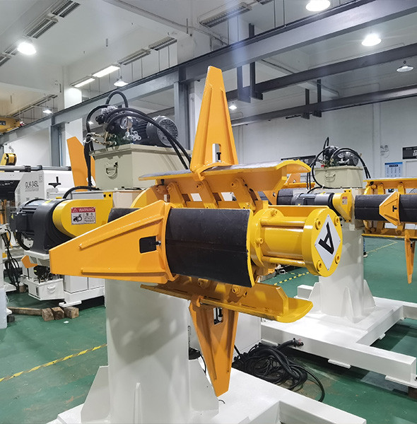
A decoiler rarely fails without warning. It gives one first, and the warning is a coil that has started to turn on the mandrel under load while the brake is still holding.
By the time an operator reports it, the segments have usually worn 0.8-1.5 mm and the coil core is bruised. This is the measurement sequence that catches it at 0.3 mm instead.
All five checks use tools already in a maintenance store: a dial indicator, a depth micrometer, a straight edge and a pressure gauge.
The whole routine takes 90 minutes on an uncoiler mandrel that is still on the machine, and it needs no crane.
Start With Radial Runout at the Segment Face
Mount the dial indicator on the machine frame, not on the mandrel, and put the stylus on the outer face of segment one at mid-width.
Turn the mandrel by hand through one revolution and read the total indicator movement. A new mandrel holds 0.10-0.15 mm. Anything above 0.30 mm is the point where a 1,200 mm coil starts to run out of round.
Repeat on all segments. Wear is almost never even, and the segment that carries the coil weight at the 6 o'clock position wears first.
A single high segment is a different fault from a uniformly high set. One segment proud by 0.2 mm is usually a bent or badly shimmed segment, not wear, and grinding it will not fix the runout.
Write the number down with the coil diameter it was measured at. Runout on an unloaded mandrel and runout with 4 t of coil hanging on it are two different readings, and the loaded one is the one that matters.
Read Segment Height Against the Wedge
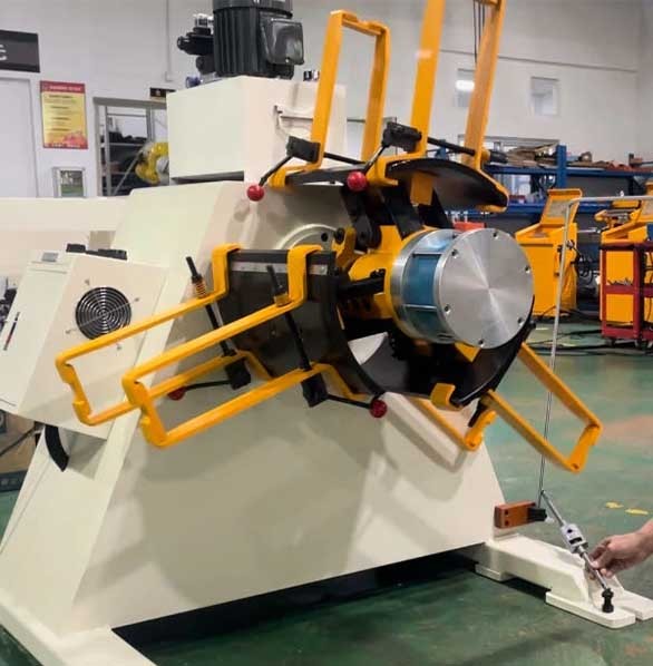
Segment wear shows up as a step between the segment face and the wedge that pushes it outward. Measure both at the same axial position with a depth micrometer.
New, the segment face and the wedge land sit within 0.05 mm of each other. After two years of 4 t coils, a 0.4-0.8 mm step is normal.
A step above 1.0 mm means the segment is bottoming on the wedge before it grips the coil. The symptom is a mandrel that will not hold a coil whose core is at the top of the tolerance range.
Check the wear pattern across the width as well. Wear concentrated at the outer 100 mm suggests the coil is being loaded off-centre, which loads one edge and leaves the other doing nothing.
Shimming buys time on a worn mandrel and it buys it unevenly.
A 0.5 mm shim under one segment changes the grip circle by 0.5 mm at that point, and an out-of-round grip circle is what produces the bruising on the coil core.
How much mandrel runout is acceptable on a 5 t decoiler?
0.10-0.15 mm new, 0.30 mm as an action limit, 0.50 mm as a stop-the-line limit on coils above 1,000 mm diameter.
At what segment step should the mandrel be re-ground?
At 1.0 mm of step, or earlier if the machine handles 0.5 mm strip where core bruising transfers into the first 20 m of coil.
How often should the grip circle be measured?
Every 500 running hours, and immediately after any event where a coil has spun on the mandrel. That is roughly quarterly on a two-shift pattern.
Can a worn mandrel be repaired in place?
Runout can be improved by re-grinding the segments in place with a tool post grinder. Segment-to-wedge steps above 1.5 mm need the mandrel stripped.
What hydraulic hold pressure should a 5 t mandrel keep?
Typically 80-120 bar at full expansion, holding within 5 bar over 5 minutes with the pump isolated. A 15 bar drop in 5 minutes is a seal bypass.
How long does a set of segments last?
Six to ten years on 3-5 t coils at 20-30 coil changes a week. Coils above 8 t or abrasive galvanised stock cut that to four to six years.
Check the Grip Marks on the Coil ID
The coil core is the mandrel's own test record, and it costs nothing to read. Ask the operator to keep the last three spent cores instead of sending them straight to scrap.
A healthy grip leaves four to eight even, shallow bands around the full circumference. Slip leaves a polished patch with a hard start line where the mandrel caught again.
A polished patch on one side only points to an eccentric grip circle or a coil loaded off-centre. Bands that fade at the outer edge point to segment wear concentrated at mid-width.
Bruised or crushed cores on aluminium and thin-wall steel cores point the other way: the mandrel is gripping too hard, not too little, and the expansion pressure needs reducing before the core collapses further.
| Measurement | New specification | Action limit | What it costs if ignored |
|---|---|---|---|
| Radial runout, unloaded | 0.10-0.15 mm | 0.30 mm | Out-of-round pay-off, strip wander at the entry |
| Segment-to-wedge step | 0.05 mm | 1.00 mm | Mandrel will not grip top-tolerance cores |
| Hold pressure decay, 5 min | Under 5 bar | 15 bar | Coil spins under brake load, core bruising |
| Grip band pattern | 4-8 even bands | Any polished patch | Slip marks transfer to the first 20 m of strip |
| Coil core damage | No visible bruising | Visible ovality | Downstream feeding faults blamed on the wrong machine |
Photograph the core and keep it with the measurement sheet. Two photographs six months apart settle an argument about whether the mandrel is degrading or the coil supplier changed its core spec.
Hold Pressure and the Log That Sets the Trigger
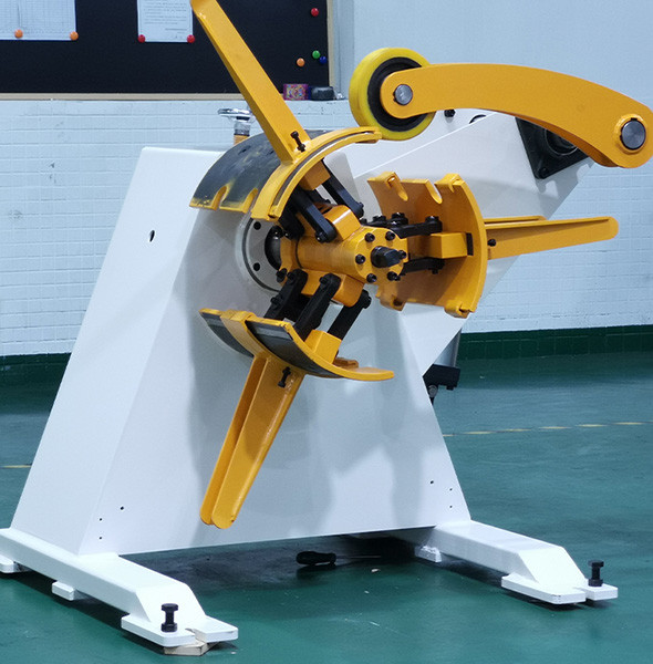
Expand the mandrel on a scrap core, isolate the pump, and watch the gauge for five minutes. A drop under 5 bar is a healthy cylinder and seal set.
A drop of 15 bar or more means oil is passing the piston seal, and the mandrel loses grip progressively as the coil turns. That is the failure mode that produces a coil spinning on a mandrel at 3 a.m.
Record four numbers every 500 hours: runout, segment step, hold pressure and coil core condition. Four numbers across twelve months is a trend; one number is an opinion.
Set the replacement trigger before the data exists, so the decision is not made during a breakdown. A workable trigger is runout above 0.30 mm plus a segment step above 1.0 mm on the same mandrel.
- Measure with the mandrel unloaded, then repeat with a coil on it.
- Log the coil weight with every reading; a 2 t shop and a 6 t shop wear differently.
- Keep three spent cores as evidence, not one.
- Check hydraulic hoses at the same interval; a weeping hose reads as a seal fault.
On a heavy duty uncoiler the same four numbers apply, with the limits widened by roughly 30%. A 10 t machine tolerates 0.40 mm of runout because the coil mass dominates the geometry.
Parts availability decides how early you act. Segment sets for a standard 508 mm mandrel are usually ex-stock; a bespoke 610 mm expansion set can be 8-12 weeks, and that wait is the real reason to measure early.
A segment set for a 508 mm mandrel runs 900-2,400 USD depending on whether the wedge and scroll are included. Re-grinding in place, with the mandrel still on the machine, runs 300-600 USD and buys one to two years.
That arithmetic decides the maintenance policy. On a machine with two coil changes a day, re-grinding every third year and replacing the set at year eight is cheaper than replacing segments at the first sign of a step.
What These Measurements Cannot Tell You
None of the five checks finds a crack inside a segment or a fatigue failure in the wedge linkage. Those fail without warning and without a trend.
Runout also says nothing about grip force on a coil whose core is out of round by 2 mm. An oval core loads two segments and leaves two loose, and the mandrel reads perfectly on a round test ring.
The numbers mislead in one more direction: a mandrel that measures well can still slip if the coil core is thin-wall aluminium. Core crush is a coil problem, and no amount of mandrel maintenance prevents it.
Finally, a good measurement sheet does not fix a worn brake. A decoiler that grips perfectly and brakes badly produces the same loose loop as a slipping mandrel, and the two faults are frequently confused.
Measure the mandrel, then measure the brake before changing any parts.
The capacity, mandrel and control decisions that sit upstream of both are covered in the coil line guide library, which starts from the coil rather than the machine.
When a coil core has already been damaged, the decision to reuse it is separate from the mandrel question, and it is worth costing before the coil goes back on the machine.
That call is worked through in our coil line knowledge base.
Where to go next
Mandrel condition is one input to the specification decision, and it is the one that changes with age rather than with the order. The capacity-to-control sequence is in our decoiler knowledge base.
The Coil Line Guide Library