How to Read an NC Straightener Feeder Layout Drawing?
- Share
- publisher
- David Park - Senior Stamping Engineer, FANTY Machinery
- Issue Time
- Sep 12,2026
Summary
A field guide to reading a coil line layout drawing before you buy: the five dimensions that decide fit, how pass line height drives cost on a retrofit, and the warning signs in a drawing set prepared to close a sale.
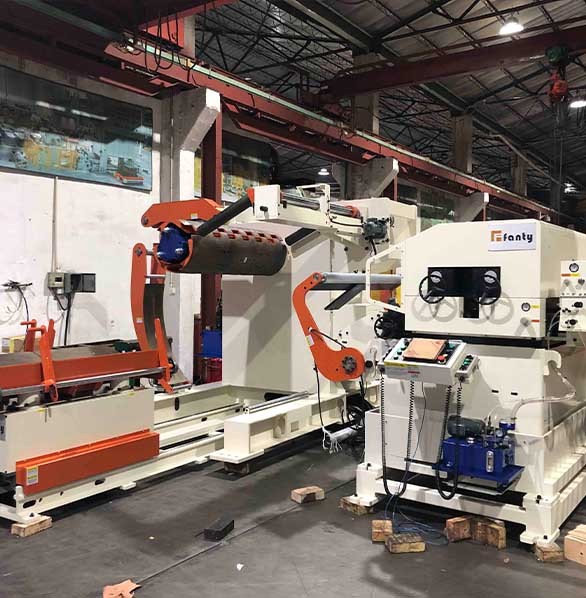
Last month I spent a Tuesday morning in a buyer's conference room in Ohio, working through a 42-sheet drawing set for a 3-in-1 decoiler straightener feeder. The quotation looked clean. The drawing did not. The coil car needed 3.4 m of travel to clear the mandrel, and the aisle behind the press offered 2.6 m. Nobody had spotted it, because the general arrangement sheet showed the machine outline and nothing else. We found it three weeks before the foundation was poured, which is exactly what a layout drawing is for.
If you are buying an NC Straightener Feeder, the layout drawing is the one document that tells you whether the machine will fit, feed and stay serviceable in your plant. A specification sheet describes what a machine can do. A drawing describes whether it can do it where you plan to put it. Here is how I read one, sheet by sheet, and which details I refuse to sign without. If you want to see the machine families this applies to, our coil feeding equipment range is a reasonable starting point.
Why the Drawing Outranks the Spec Sheet
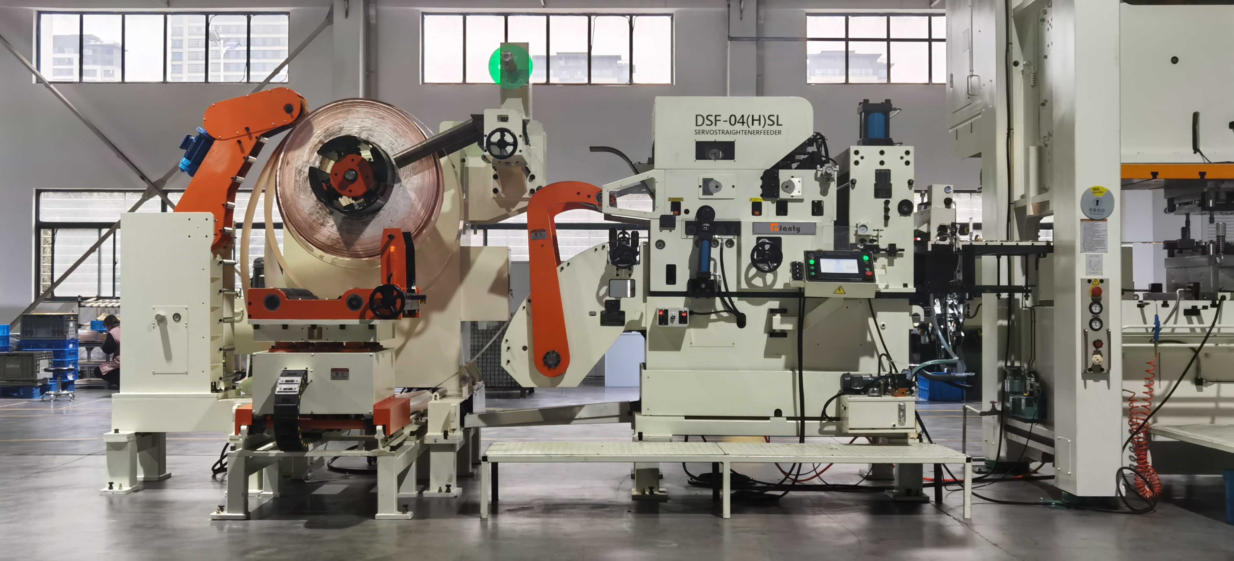
A specification sheet is a list of capabilities: strip width, thickness range, coil weight, feed speed, straightening roll count. A layout drawing is a list of consequences. It tells you how much floor the machine consumes, where the strip actually travels, how far the coil car has to move, how deep the pit must be, and which side a maintenance technician has to stand on to reach the straightener rolls.
I have watched two otherwise similar projects head in different directions because of this difference. One buyer reviewed fourteen sheets before signing and noticed that the hydraulic power unit had been placed on the operator side, blocking the die-change aisle. The fix cost nothing at that stage. Rotate the unit ninety degrees, redraw the sheet, done. The second buyer signed after reviewing the quotation and the outline sheet. Their pit came out 200 mm too shallow for the loop at full line speed. The retrofit needed a diamond saw, a weekend shutdown, a new floor drain and a landlord's approval.
Neither buyer was careless. The first one simply knew which sheets to open, and opened them before the money moved.
Five Dimensions That Decide Whether It Fits
Before you study anything else on the drawing, find these five numbers. If any one of them is wrong, the rest of the sheet is decoration.
| Dimension | Which sheet carries it | How buyers get it wrong |
|---|---|---|
| Machine footprint | General arrangement | Comparing the quoted footprint without adding coil car, hydraulic unit and control cabinet |
| Pass line height | Elevation view | Assuming it already matches the press that is standing there |
| Coil car travel | Plan view | Measuring to the mandrel centre instead of to the point where the coil eye clears it |
| Pit depth | Foundation drawing | Using strip thickness in the calculation instead of the free loop diameter |
| Service clearance | Plan plus elevation | Leaving no room to slide the straightener roll pack out sideways |
The footprint figure on a quotation is almost never the figure you need. It normally covers the machine body. It does not cover the hydraulic power unit, the control cabinet, the coil car sitting in its retracted position, or the operator's walking route. Add all four before you hold the number up against the space you have.
Matching Pass Line Height to the Press You Already Own
Pass line height is the elevation where strip leaves the feeder and enters the die. On a new line, the machine and the press are designed together and the dimension is trivial. On a retrofit, it is the most expensive number on the drawing.
Suppose the drawing shows a pass line 150 mm above your press entry. You have three options. Raise the press, which almost nobody does. Build a plinth under the feeder, which is usually the cheapest answer but changes operator working height, guarding and coil car geometry. Or ask the builder to adjust the machine frame during manufacture, which is free before the steel is cut and expensive afterwards.
I always ask for the pass line dimension in two forms: the nominal value and the adjustment range. A feeder that holds tight feed length tolerance still has to be mechanically aligned to the die entry, and a machine with only 20 mm of vertical adjustment gives you almost no room to correct a floor that slopes toward a drain. Ask for the elevation view at the same time you ask for the quotation, not three weeks after the order.
Coil Car Travel, Pit Depth and Service Access
These three are the ones that turn a clean installation into a change order. Check them in this order.
- Coil car travel is measured from the fully retracted position to the point where the coil eye clears the mandrel end, not to the mandrel centre. On a 1,500 mm coil that difference is roughly 750 mm of extra stroke, and it is the number that decides whether the car fouls a column.
- Pit depth is set by the free loop diameter at maximum line speed, plus margin for strip with residual curvature. Size it for the fastest product you expect to run in five years, not the slowest one you run today.
- Service clearance on the roll pack side. If a wall sits 600 mm from the frame, a routine roll change becomes a crane lift and a lost shift.
- Cable and conduit routes from the control cabinet back to the press control. They must not cross the coil car path, and they must not run through the pit.
- Air and hydraulic drops. These appear on almost no drawing set and on almost every site installation invoice.
Warning Signs Inside a Drawing Set
A set prepared for a real project looks different from one prepared to close a sale, and the difference is visible in about ninety seconds.
Plan views with no elevation views. If the set never shows the machine from the side, nobody has thought about pass line height or pit depth. No foundation load table. Every machine needs a load per anchor point, because your structural engineer will ask for it and the vendor should already know the answer. No utility schedule. Air consumption, hydraulic pressure and connected electrical load belong on the drawing, not buried in an email chain three months later.
The clearest signal of all is a revision block with nothing in it. If a drawing has never been revised, it has never been checked against a real site. That is not a reason to reject a vendor, but it is a reason to read every sheet yourself.
What to Confirm Before You Sign
Run this list before you release the purchase order, and keep the answers in the contract file.
Ask for a site-specific drawing rather than a catalogue drawing, with your plant's column grid drawn on it. Confirm the drawing revision number in writing and make that revision part of the contract, so a later substitution is a documented change rather than an argument. Walk the route the coil car will take with a tape measure, on the floor, while the aisle is still empty. Confirm that every wearing component, including rolls, bearings and brake pads, has a maintenance position shown on the sheet. Finally, ask the vendor to mark which dimensions are adjustable and which are fixed.
We have been building coil handling equipment for twelve years, and more than 200 of those lines are running in plants where somebody read the drawing before the foundation was poured. That is not a coincidence. It is a habit, and it is the cheapest one in the project.
Questions buyers ask before signing
Which sheet in a layout set matters most?
The elevation view. It carries pass line height, pit depth and service clearance, and those are the three dimensions that are hardest and most expensive to change once the machine is on the floor.
Can pass line height be corrected after installation?
Only within the adjustment range built into the machine frame, typically a few centimetres. Anything larger needs a plinth, and a plinth changes operator working height, guarding and coil car geometry all at once.
How much clearance does a straightener roll change need?
Plan for the full roll pack length plus at least 300 mm of hand clearance on the service side. A pack that cannot slide out turns a twenty-minute maintenance task into a crane lift and a lost production shift.
Should the hydraulic power unit appear on the general arrangement?
Yes. It draws electrical power, generates heat, makes noise and needs service access. If it is missing from the drawing, it will be missing from your floor plan as well, and it will land in the first available gap.
Is a standard catalogue drawing ever good enough?
For a greenfield line where the press is also new, sometimes. For a retrofit against an existing press and an existing building, always insist on a site-specific set with your column grid on it.
Want your layout reviewed before you sign?
Send us your press entry height, aisle dimensions and coil sizes. Our engineering team will confirm pass line, pit depth and coil car travel against the drawing set, and flag anything that will not fit before steel is cut.
Request a layout review