How to Test NC Servo Feeder Accuracy Before Production?
- Share
- publisher
- David Park - Senior Stamping Engineer, FANTY Machinery
- Issue Time
- Aug 31,2026
Summary
A step-by-step procedure to test NC servo feeder accuracy before production, with acceptance thresholds, drift troubleshooting, and the tools you need.
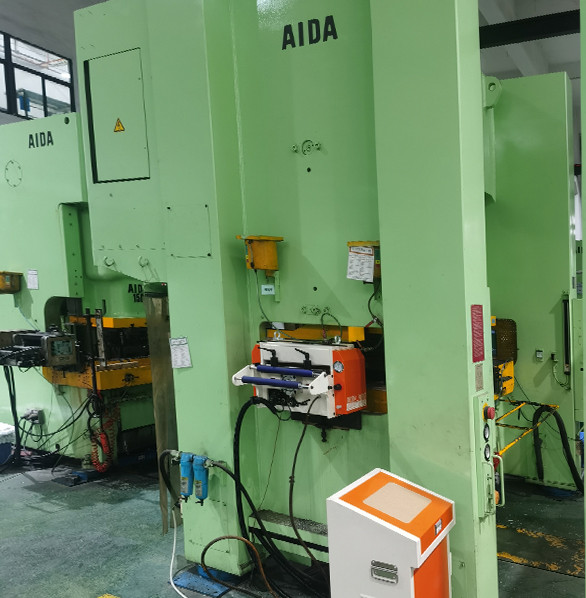
Before you commit a new NC servo feeder to full production, you need proof that it feeds accurately. A feeder that drifts by half a millimetre can ruin progressive dies, produce thousands of scrap parts, and undermine confidence in the whole line.
This guide explains how to test NC servo feeder accuracy before production starts, what results are acceptable, and how to separate a machine problem from a material or setup problem.
The same test procedure applies whether you are commissioning a new feeder, troubleshooting an existing one, or auditing a 3-in-1 decoiler straightener feeder line. It takes less than an hour, needs only basic tools, and gives you a measurable baseline you can compare against for the life of the machine.
What Feed Accuracy Actually Means
Feed accuracy is usually stated in two parts. Positioning accuracy is how close the fed length comes to the programmed value on a single feed, and repeatability is how consistent that value is across many cycles.
FANTY's NC servo feeder specification quotes ±0.05 mm feeding accuracy, which refers to the repeatable positioning band under stable conditions.
That number only means something in context: material thickness, straightening quality, feed speed, and press condition all influence the result you will actually measure on the shop floor. The test procedure below isolates the feeder's own performance so you can judge the machine fairly.
It is also important to distinguish between feed length error and die-related error. If the die itself has worn guidance or the strip is buckling before entering the die, the part will be wrong even when the feeder is perfect. That is why a proper accuracy test measures the strip position directly, not the finished part.
Tools You Need for the Accuracy Test
You do not need laboratory instruments for a practical feeder accuracy test. The essential tool list is short:
- A calibrated steel rule or vernier caliper readable to 0.05 mm for measuring fed strip length.
- A fine-tip marker or a scribe to make a reference mark on the strip edge without distorting it.
- The feeder's data sheet so you can compare measured values with the claimed specification.
- A test material that is representative of production: same width, thickness, and surface condition.
- A recording sheet to log every measurement, including date, program, speed, and material details.
Use the same material family as your real production.
Step-by-Step Accuracy Test Procedure
Follow this procedure in the exact order. Running the steps out of sequence invalidates the results because each step depends on the previous one.
Step 1 — Stabilise the setup. Thread the strip through the decoiler, straightener, and feeder as in normal production. Run the line for ten minutes at a moderate speed so the straightener rolls warm up and the strip settles. Testing a cold line measures the warm-up state, not steady production.
Step 2 — Set a reference program. Program a feed length that is realistic for your parts, for example 200 mm, at your typical production speed. Make a fine reference mark on the strip edge at the feeder exit before the first feed.
Step 3 — Run a batch of feeds. Execute the programmed feed ten times without forming parts, letting the strip advance freely. After each feed, measure the distance from your reference mark to the new strip position with the caliper and record the value.
Step 4 — Calculate the error band. The difference between the largest and smallest measured values is your repeatability. The difference between the average measured value and the programmed length is your positioning error. Compare both against the specification.
Step 5 — Test at two speeds. Repeat steps 2 to 4 at roughly half speed and at full production speed. Many feeders hold accuracy at low speed but drift at high speed, so this step reveals dynamic error that a single-speed test misses.
Step 6 — Record and file. Log everything on the recording sheet with the date and program number, and keep the sheet with the machine documentation. This becomes your baseline for future audits and for judging whether a drift problem is new or long-standing.
Interpreting the Results
| Measurement | Acceptable Result | Action Required |
|---|---|---|
| Repeatability band | Within ±0.05 mm of the mean | None — feeder is performing to spec |
| Repeatability band | 0.05–0.15 mm | Check strip guidance, straightener settings, and pinch pressure |
| Repeatability band | Above 0.15 mm | Investigate: servo tuning, encoder coupling, mechanical wear, or clutch slip |
| Positioning error | Consistent offset under 0.1 mm | Add program compensation if the offset is stable |
| Speed drift | Error grows more than 0.05 mm from low to high speed | Review acceleration settings and servo gain with the supplier |
| First-feed error | First feed after stop outside the band | Check for backlash in the feed mechanism or air in the clutch |
The table gives practical thresholds, but treat them as guidance rather than law. If your parts require tighter control than the standard band, test to your own tolerance. The critical discipline is consistency: run the same test the same way every time, so that a change in results means a real change in machine condition.
What to Do When Accuracy Drifts
If a previously accurate feeder starts drifting, work through the causes in order of likelihood. First, check the material: a new coil batch with different thickness or hardness changes the required pinch pressure and straightening force.
Third, check the mechanical drive path: coupling wear, gear backlash, or loose pulleys introduce error that the servo cannot correct because it measures motor position, not strip position. Fourth, check the encoder and its coupling. A damaged encoder cable or a loose encoder coupling produces exactly the intermittent length errors that are so frustrating to chase.
Finally, review the servo parameters. If the machine was recently serviced or the control software updated, tuning values may have been lost. Compare the current parameter set against the factory baseline and restore it if needed.
When none of these steps resolves the drift, involve the supplier with your test records — a structured accuracy log is the fastest way to get a correct diagnosis.
FANTY's Factory Accuracy Testing
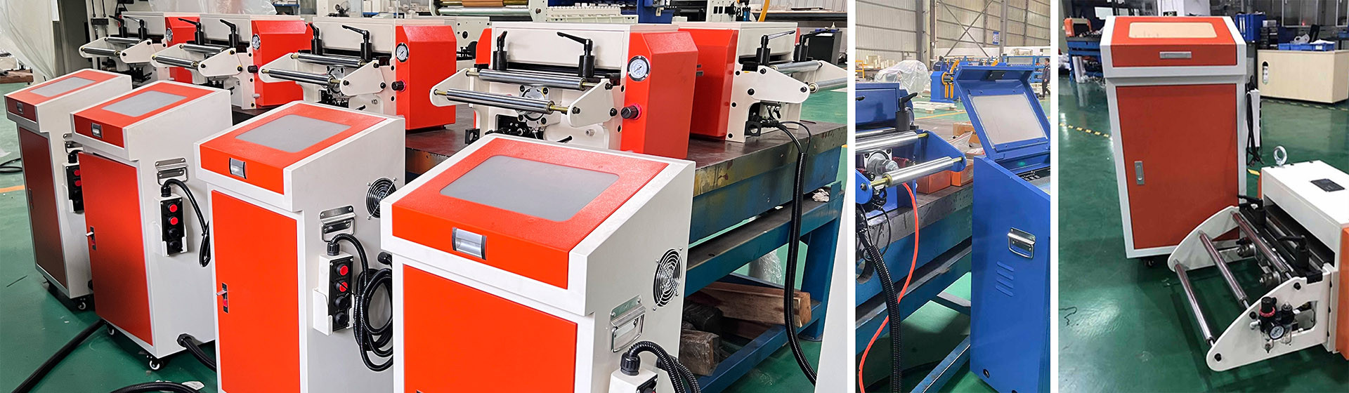
Every FANTY NC servo feeder is accuracy-tested before it leaves the factory, with the results recorded against the machine serial number and included in the handover documentation. The 45,000 m² plant, 370 staff, and 80+ R&D engineers support a controlled test environment where feed accuracy is verified at multiple speeds before shipping.
FANTY's 12 years of coil line experience and 200+ active installations across 60+ countries mean the commissioning engineers have seen the full range of shop-floor conditions.
They will run the same accuracy test procedure described here during your commissioning, establish your baseline with you, and leave you with the measurement skills to audit the 3-in-1 decoiler straightener feeder or standalone feeder line whenever you need.
CE-certified machines and unit-specific test reports are standard with every delivery.
Frequently Asked Questions
How long does the accuracy test take?
Around 30 to 60 minutes including warm-up, the ten-feed batch at two speeds, and recording. It is a small time investment compared with the scrap and die damage that a drifting feeder can cause in one shift.
Do I need special instruments for the test?
No. A steel rule or vernier caliper readable to 0.05 mm, a marker, and a recording sheet are sufficient for the standard procedure. Laboratory-grade measurement is only needed for certification or dispute resolution.
Why does accuracy change with feed speed?
At higher speed, inertia, acceleration, and servo response all play a larger role. A feeder that is well tuned for one speed can drift at another, which is exactly why the procedure tests at two speeds and why servo tuning should be done at production speed.
Should the test include the straightener?
Yes, run the full material path. The straightener affects strip shape and therefore feed behavior. Testing only the feeder with pre-straightened strip gives optimistic results that do not represent production.
What if my feeder fails the test after commissioning?
Start with the drift checklist: material change, pinch roll condition, mechanical drive, encoder, then servo parameters. If the fault persists, contact FANTY with your test log and serial number — the baseline from commissioning gives us a direct comparison.
Related reading
- setting up for fast stamping
- which part limits feeding accuracy
- how to hold feed accuracy on a coil line
Part of the the coil line guide library — the full library of coil handling, straightening and feeding guides from FANTY.
Get an NC Servo Feeder That Passes the Accuracy Test
Request the specification, factory test report, and commissioning plan for a FANTY feeder sized to your press line.
Send Inquiry to FANTY