How to Time Pilot Release on a Servo Feeder
- Share
- publisher
- David Park - Senior Stamping Engineer, FANTY Machinery
- Issue Time
- Oct 21,2026
Summary
Pilot release is a sequence, not a setting. This sets out the six steps in the order they must happen, converts the window into milliseconds at 200 and 300 SPM, lists the six symptoms of a mistimed release with the die cost of each, and states where the degree-based numbers stop applying.
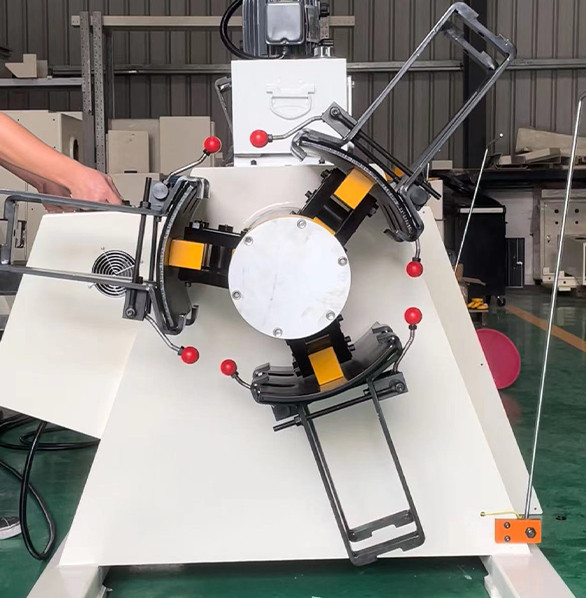
Pilot release is a sequence, not a setting. The pins must be in the strip before the rolls let go, and the rolls must re-grip before the press closes.
Get the order right and a 200 SPM press runs clean. Get it 20 ms late and you bend a pilot pin, then a die section, then a week of production.
Everything below applies to any NC servo feeder with a programmable release output, whatever the stroke or the tonnage.
Map the Stroke Before You Touch a Timer
Every timing decision is expressed in crank degrees first and milliseconds second. Degrees survive a speed change; milliseconds do not.
Write both columns on the setup sheet: degrees for the press, milliseconds for the valve. The valve is the part that fails first.
At 200 SPM one crank degree is 0.83 ms. At 100 SPM the same degree is 1.67 ms, so a 20-degree window doubles in time when the press slows.
Write the sequence on the press: pilot entry angle, roll open angle, roll close angle, bottom dead centre. Convert to time only after that.
If the press builder cannot give you the pilot entry angle, measure it. A dial indicator on the pilot head and a degree wheel settles it in an hour.
Do this once per die, not once per press. Two dies with different pilot lengths have two different windows on the same machine.
Write the numbers on the die itself. A setup sheet lives in an office; a die lives on a bolster and travels with the job.
Six Steps in the Sequence
The order below is the order that works. Swapping any two adjacent steps produces one of the symptoms in the next table.

Step 3 is the one operators skip. Opening the rolls while the servo is still settling produces a 0.2 mm shift that reads as a feed fault.
- 1. Feed completes and the servo holds position. Wait for the in-position signal; do not open the rolls while the servo is settling.
- 2. Pilot pins enter the strip. This must happen with the strip still gripped, or the strip shifts and the pins scrape the hole edge.
- 3. Rolls open. The release signal follows pilot entry by 3-8 degrees at typical speeds.
- 4. Press completes the stroke. The strip is now located by the pilots, not by the feed.
- 5. Rolls close. Close before the pilots withdraw, so the strip cannot move as the pins leave.
- 6. Feed advances. Start only on a confirmed close signal, never on a timer that assumes the rolls did close.
- ('p', 'Two of the six steps are often merged in a PLC: close and advance. Keep them apart, because an unconfirmed close will start a feed into open rolls.')
The Window at 200 SPM
Take a press with a 1,100 mm stroke at 200 SPM: 300 ms per cycle, 0.83 ms per crank degree.
Pilot entry at 100 degrees before bottom dead centre leaves 83 ms to bottom. Roll release needs 8 degrees, or 6.6 ms, after entry.
Move the entry point 20 degrees earlier and the window widens by 17 ms. That is usually cheaper than a faster valve.
That puts the usable roll-open window at 10-20 degrees. Below 10 the pins scrape; above 20 the strip is free too long and drifts.
At 300 SPM the whole sequence compresses to 200 ms. A 20-degree window becomes 11 ms, and any pneumatic delay in the release valve eats it.
That is the practical ceiling for a pneumatic release: 300 SPM, and only with a fast valve and short air lines.
Mechanical release cams reach higher speeds because there is no valve in the path. The trade is a fixed window that cannot follow a die change.
Two Dies, One Press: Switching the Window
A press running two dies on the same day needs two release windows, and the difference is usually larger than the operators expect.
A die with 12 mm pilots and one with 40 mm pilots can need 6 degrees of separation at the release signal. That is 5 ms at 200 SPM.
Store the window with the die, not with the press recipe. The press does not know which die is bolted into it this morning.
Label the die with its pilot entry angle and release offset. A painted number on the bolster saves a setup shift.
| Die pair | Pilot length | Release offset | Where it costs you |
|---|---|---|---|
| Small bracket die | 12 mm | 3 deg | Too early and the pins scrape the hole edge |
| Structural die | 40 mm | 8 deg | Rolls must open 7 ms earlier at 200 SPM |
| Progressive, 9 stations | 25 mm | 5 deg | A middle setting suits neither die exactly |
| Spring-pilot die | 18 mm | 10 deg | The springs hold the strip, so release can wait |
Verify the window on the first ten strokes after every change. A cam re-timed for one die will misfire on the other.
The other terms in that budget, from roll slip to pilot timing, are set out in the coil line guide library. Pilot release is one line of it.
What a Late Release Bends
Each symptom below maps to one timing fault. Read the symptom first, then check the step.
| Symptom | Timing cause | Where it costs you |
|---|---|---|
| Pilot pin bent at the shank | Rolls opened before pins seated | Pin set plus die downtime |
| Pilot holes elongated | Pins entering while the strip still moves | Part scrap, not just pins |
| Feed drift 0.1-0.3 mm | Rolls closing after the pilots withdraw | Rework on every part |
| Scuffed strip top surface | Rolls still gripping during pilot entry | Cosmetic reject on visible parts |
| Die section cracked at the pilot | Strip pulled against a seated pin | Die repair, 2-5 days |
| Random misfeeds at high speed | Valve delay longer than the window | Speed derate to 200 SPM |
The last row is the one that hides. The line runs, the parts pass, and the only evidence is a speed limit nobody can explain.
Log the speed limit with the date beside it. When the limit moves from 300 to 200 SPM, something changed in the valve, not in the die.
Checking It Without a Camera
A high-speed camera is the right tool and rarely on site. Three cheaper checks find the same faults.
First, chalk the strip. A 10 mm chalk mark at the pilot hole shows scrape direction after a single stroke.
Second, listen at low speed. A double click in the die means the pins are entering twice, which is a release that fires early and re-fires.
Chalk and sound find the gross faults. Only the position-error log finds a release that is 4 ms late and still passing parts.
Third, log servo position error. A spike at pilot entry means the strip is pushing the pins, which points at a late release.
Log it for 200 strokes, not 10. A release that is 4 ms late shows as one spike in ten, which a short sample misses.
Run all three at 60 SPM first. Timing faults that hide at 200 SPM are obvious at a third of the speed.
Release outputs and valve options differ by model. Our feeder range lists what each one carries as standard.
Where This Sequence Does Not Hold
The sequence assumes a mechanical press with a fixed stroke and a cam-driven release. Three cases break it.
Hydraulic presses with programmable dwell move the window by 30-50 degrees, and the degree figures above no longer apply.
A servo press with a programmable stroke is a fourth case. It needs the window mapped against the motion curve, not the crank angle.
Long pilots, over 40 mm of engagement, need the rolls open earlier, because the strip has to be free while the pins travel.
Short pilots under 10 mm are the mirror case. The pins seat so fast that the release can come later than the table suggests.
A die with spring-loaded pilots needs the release later, not earlier. The springs hold the strip while the pins seat, so the rolls can stay closed longer.
On a 0.5 mm strip with a 6 mm pilot the whole window can be 4 degrees. At that point the mechanical cam, not the servo, sets the limit.
Five questions come back from every commissioning visit. The answers below are the ones we check against on site.
How many milliseconds is one crank degree at 200 SPM?
0.83 ms. At 300 SPM it is 0.56 ms, which is why a 20-degree window shrinks from 17 ms to 11 ms.
At what speed does pneumatic pilot release stop working?
Around 300 SPM with a fast valve and short lines. Past that the valve delay exceeds the window and misfeeds turn random.
How much feed drift does a late roll close add over 100 strokes?
0.1-0.3 mm per stroke. It shows as a slow length creep that no feed-length correction can hold, because the loss is random.
Can pilot release be timed from the servo alone?
No. The servo knows where the strip is, not where the press crank is. Use a crank encoder or a cam signal for the release.
What pilot engagement length needs an earlier release?
Above 40 mm. The strip must be free for the whole travel of the pins, or the holes take a taper on one side.
Where to go next
This is one step inside the wider feed-accuracy chain, from coil to die. The full error budget and how each term is measured sits in our coil line knowledge base.
The Coil Line Guide Library