How to Wire an NC Servo Feeder to the Press Safety Circuit?
- Share
- publisher
- David Park - Senior Stamping Engineer, FANTY Machinery
- Issue Time
- Sep 4,2026
Summary
How the NC servo feeder and press safety circuits communicate: ready signals, stop signals, light curtain interfaces, and wiring rules for safe synchronized stamping.
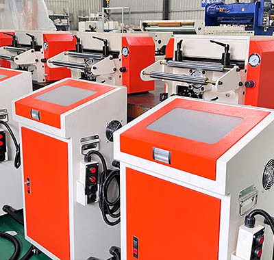
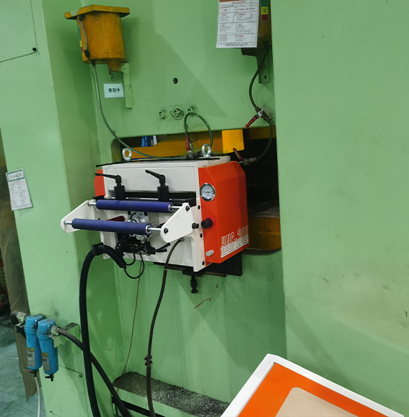
An NC servo feeder and a press are two machines that must act as one. The feeder advances the strip, the press stamps, and the two repeat hundreds of times per minute in perfect alternation.
That coordination is not an option; it is a safety requirement, because a feeder that advances while the die is closing, or a press that strokes while the strip is still moving, creates a crash that can destroy tooling and endanger the operator.
Every signal that makes this coordination possible travels through the safety circuit, and the way that circuit is wired determines whether the line is safe, legal, and reliable. This guide explains the signals involved, the wiring rules that matter, and the mistakes that cause feeder-press miscommunication.
Whether you are installing a new coil line or adding a feeder to an existing press, the same principles apply. The details here follow the logic used on CE-compliant FANTY lines, where the feeder, the straightener, and the press exchange hard-wired safety signals before any motion is allowed.
Why the Feeder Must Talk to the Press
The press and the feeder each have a job that depends on the other's state. The feeder must not feed while the press is mid-stroke, because the strip would collide with the descending die.
On a modern line, the conversation looks like this. The press tells the feeder that it is safe to feed when the slide is at top dead center. The feeder advances the strip, stops, and then tells the press that the strip is in position. Only then does the press release its next stroke.
The sequence is fast enough for 200 strokes per minute, which means the whole exchange happens in a few hundred milliseconds, but the principle is exactly the same as two workers passing a part: each one waits for the other to say ready.
The Core Signals You Need to Understand
Four signals form the backbone of feeder-press interlocking. Understand these and you can read any wiring diagram the builder gives you.
- Press top-dead-center signal. Sent from the press cam switch to the feeder as the release to begin the feed stroke.
- Feeder in-position signal. Sent from the feeder to the press to confirm the strip has reached the programmed position and is clamped.
- Common stop line. Any emergency stop, guard opening, or fault on either machine pulls this line and stops both machines together.
- Ready and fault signals. Status outputs from each machine so the operator can see at a glance whether the line is ready to run or which machine is holding it.
These signals should be hard-wired through safety relays or a certified safety PLC.
Wiring Rules That Keep the Line CE-Compliant
Safety wiring follows rules that exist because people have been injured when they were ignored. The table below summarizes the rules that matter most on a feeder-press interface.
| Rule | Why it matters | Typical implementation |
|---|---|---|
| Emergency stop must be hard-wired | A software stop can fail silently or lag | Dual-channel e-stop circuit through a safety relay |
| Safety signals use normally-closed logic | A broken wire reads as a stop, not as a run command | N/C contacts wired in series |
| Guards and light curtains interrupt both machines | Opening a guard must stop the press and the feeder together | Guard switch in the common stop chain |
| No single component failure creates an unsafe state | Redundancy prevents a stuck relay from allowing a stroke | Dual-channel monitoring with cross-check |
| Faults require a manual reset | The line must not restart itself after an incident | Reset button outside the guarded area |
| Documents match the installed wiring | Maintenance crews must trust the diagram | As-built schematic with revision date |
CE marking for a machine line is not a sticker; it is a technical file that includes the risk assessment, the circuit diagrams, and the component certificates. When a feeder is added to an existing press, the combination often needs a fresh risk assessment, because the line as a whole is a new machine in the eyes of the regulation.
How the Feeder Knows the Press Is Safe to Feed
The feeder receives its permission to move from the press cam signal at top dead center, but that permission is only valid if the safety chain is closed.
This is why the feeder's HMI shows a line status screen rather than just a feed counter. When the operator sees the press icon, the feeder icon, and the guard icons all green, the line is interlocked and ready. When one is red, the screen shows which condition is missing, turning a frustrating no-start problem into a ten-second diagnosis.
Common Wiring Mistakes and How to Avoid Them
Most feeder-press problems are not component failures; they are wiring and configuration mistakes made during installation. The five below are the ones our service engineers see most often in the field.
- Using the wrong cam position. The feed-release signal must come from true top dead center, not from a cam set for another purpose.
- Sharing a network instead of hard-wiring safety. Safety signals on a standard network add latency and failure modes that hard-wired relays do not have.
- Incorrect polarity on the in-position signal. Reversing a normally-closed and normally-open contact can let the press stroke while the strip is still moving.
- Ground loops between machines. Separate grounding points create circulating currents that cause false signals on the interface.
- Skipping the commissioning test. The full interlock test, stroke by stroke, is the only way to prove the circuit before production starts.
Each of these is easy to prevent during installation and expensive to find after a crash.
Commissioning: The Test That Proves the Circuit
Commissioning is not the moment the machines are bolted down; it is the moment the safety circuit is proven. A proper feeder-press commissioning includes the following tests, each documented with the result.
- Signal continuity check: every wire on the interface is verified against the diagram.
- E-stop test from each station: the press e-stop, the feeder e-stop, and any remote stop all halt both machines.
- Guard interruption test: opening each guard during a running feed stops the line within the required distance.
- Single-cycle test: the sequence runs one stroke at a time with the operator watching the strip position.
- Continuous test at low speed: the interlock holds over a hundred strokes at reduced speed.
- Full-speed test: the line runs at production speed and the feed pitch is verified against the die.
FANTY commissioning engineers run this list on every line we install and leave the signed test report with the buyer. If a future fault appears, the report is the first place the maintenance team looks, because it documents exactly how the circuit should behave.
Frequently Asked Questions
Can the feeder and press communicate over a network instead of hard-wired signals?
Production and status data can travel over a network, but the safety-relevant signals, the ones that permit motion, should always be hard-wired through safety relays or a certified safety PLC. This is both a reliability choice and a compliance requirement on CE-marked lines.
What happens if the press cam signal is lost while running?
The feeder treats a lost cam signal as a stop condition and holds the strip in position. The line will not restart until the cam signal is restored and the operator performs the required reset, which prevents a half-finished feed from continuing blindly.
Do we need a new risk assessment when adding a feeder to an old press?
Yes. Combining a feeder with a press creates a new machine from a safety perspective. Most reputable suppliers and regulators expect a fresh risk assessment covering the interlocked line, including the guards and the interface circuit.
Who should do the interlock wiring, the press vendor or the feeder vendor?
The two vendors must agree on the interface specification, and each should wire its own side of the terminal strip. One party, usually the line integrator, takes responsibility for the final interlock test so there is no gap between the two machines.
How do light curtains connect into the feeder-press system?
Light curtains at the die area or the coil entry connect into the common stop chain, so any beam interruption stops both the press and the feeder. The curtain's safety output must be wired through the same certified safety relay logic as the other guards.
Related reading
Part of the the coil line guide library — the full library of coil handling, straightening and feeding guides from FANTY.
Install an NC Servo Feeder That Is Safe from Day One
FANTY supplies NC servo feeders and straightener feeders with a defined interface specification, so wiring into your press safety circuit is clear from the start. Send us your press model and control voltage and we will confirm the interface and include the interlock test in the commissioning plan.
Confirm Compatibility with Your Press