What Causes Camber in an NC Straightener Feeder?
- Share
- publisher
- David Park - Senior Stamping Engineer, FANTY Machinery
- Issue Time
- Sep 14,2026
Summary
Why camber is a width-direction problem that whole-gap adjustments cannot fix, the five sources ranked by how often they turn out to be the answer.
Flatness gets all the attention on a coil line. Camber causes more scrap. A strip that is perfectly flat but curves 4 mm to the metre will not track through a progressive die, will drag on one side of the entry guide, and will eventually produce a part with a burr on one edge and a short wall on the other. By the time the operator notices, the coil is half consumed and the tool has taken an hour of uneven wear.
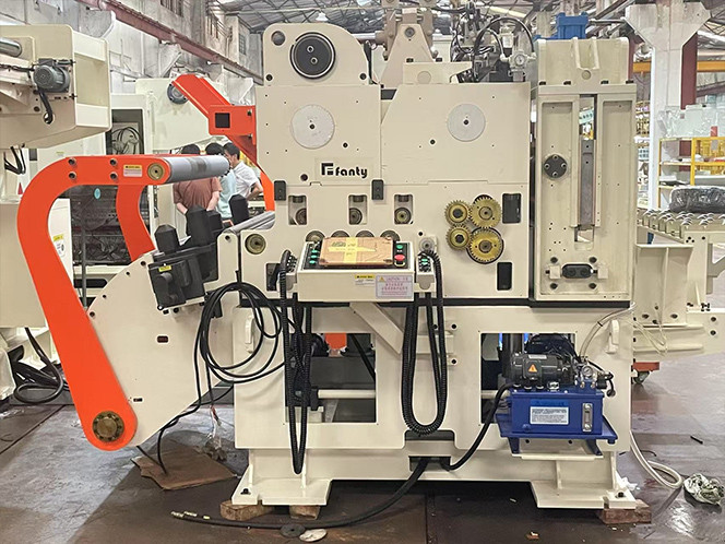
Camber is a width-direction problem, which is why it behaves differently from anything else on the line. Flatness is about length differences across the strip; camber is about length differences along the two edges. The strip leaves the straightener with the operator side slightly longer than the drive side, and the only way for a strip to absorb that difference is to curve toward the shorter edge. Everything that follows from that single geometric fact explains why camber is set by roll alignment, strip profile and tension rather than by the leveler gap alone. The straightener section is where most of the fixable causes live, and our coil feeding equipment range shows how the roll bank is built on the machines we supply.
Two Edges, Two Lengths
Take a strip that has been bent through the straightener and imagine it as two independent ribbons joined along the centre. If the straightener treats both ribbons identically, they come out the same length and the strip runs straight. If the treatment differs even slightly, one ribbon ends up longer and the strip curves.
How slight is slight? On a 300 mm wide strip, a length difference of 0.03 percent between the two edges, which is 0.3 mm over a one-metre length, produces visible camber. That is a difference the eye cannot see on the machine and a feeler gauge can barely find. It is also why camber problems so often survive several rounds of adjustment: the operators are looking for something visible when the cause is a tolerance-level asymmetry.
The practical consequence is that camber cannot be corrected by changing the leveler gap overall. Raising or lowering the whole upper roll bank changes both edges equally. Camber responds to differential adjustment: roll tilt, roll crown, or a difference in the material itself.
Five Sources, Ranked by Frequency
Across the lines I have helped commission, camber traces back to a short list of causes. The order below reflects how often each one turns out to be the real answer after the obvious checks are exhausted.
| Source | Signature | How to confirm | Corrective action |
|---|---|---|---|
| Straightener roll tilt side to side | Camber constant through the whole coil, same direction every time | Feeler gauge the gap at both ends of each roll with the machine at rest | Re-shim and re-level the roll bank; verify with a dial indicator on the roll face |
| Uneven strip thickness across width | Camber changes with coil supplier but not with machine settings | Micrometer the strip at five points across the width at the coil head | Work with the mill on a crown specification; adjust roll crown to compensate |
| Roll crown worn or machined incorrectly | Camber worst at high tension, better when tension is reduced | Straightedge and micrometer across the roll face at three positions | Regrind or replace the roll pair with a matched crown |
| Unequal tension across the strip | Camber shifts with loop height and coil radius | Watch camber at the start and end of a coil on the same job | Fix brake control and check mandrel runout, which biases tension side to side |
| Entry guide misalignment | Camber appears only after a guide or edge-roller change | Measure guide opening at both ends and check squareness to the pass line | Realign the guide; edge rollers should guide, not steer |
Note the shape of this table. Only one of the five sources lives inside the straightener. The other four come from the coil, the brake, the mandrel or the entry guide. That distribution is the reason camber gets misdiagnosed: the adjustment that would fix a roll tilt is the one most operators reach for, and it does nothing when the cause is a strip profile from the mill.

How Roll Crown Turns Into Camber
A straightener roll is not a cylinder. It is machined with a slight crown, meaning the diameter at the centre is a few hundredths of a millimetre larger than at the ends. The crown exists to compensate for roll deflection under load, so that the strip sees uniform pressure across its width when the machine is working.
That compensation is only correct at one load. Run a narrower strip and the roll deflects less, so the centre of the strip receives more pressure than it needs. Run a wider or harder strip and the roll deflects more, so the edges are under-worked. Both conditions create a differential bend across the width, and differential bend creates a length difference, and a length difference creates camber.
The number that matters is the crown value. A typical straightener roll carries a crown of 0.03 to 0.08 mm over its face depending on roll diameter and bearing span. If that crown is ground to 0.02 mm, the roll under-compensates at full width and the strip edges receive less work than the centre. If it is ground to 0.12 mm, the centre is over-worked and the strip curves the other way. Neither error is visible on a straightedge; both show up in the strip.
This is why camber problems often appear after a roll regrind that was performed correctly to the drawing but with the wrong crown. The rolls look perfect, measure round, and produce a strip that curves.
Why Camber Changes Through a Coil
If camber is constant from the first metre to the last, the cause is mechanical and static. If it drifts, the cause is geometric and changing. Most camber complaints fall into the second group and get treated as the first.
Three things change as a coil unwinds. The coil radius falls, which changes the payoff geometry and the entry angle into the straightener. The back tension required to hold the loop falls with it, which changes the tension the strip carries through the roll bank. And the mandrel's grip on the inner wraps is different from its grip on the outer wraps, which can bias the strip sideways by a fraction of a millimetre as it leaves the coil.
On a line running 1.0 mm material at 300 mm width, I have measured camber going from 1.2 mm per metre at the coil head to 3.5 mm per metre at the tail on the same job with no setting changed. The cause turned out to be mandrel runout of 0.35 mm combined with a falling back tension, so the strip entered the straightener at a slightly different lateral position at the head and the tail. Fixing the mandrel brought the tail figure down to 1.6 mm per metre, and the remaining drift was handled by tightening the brake control band.
This is why a camber measurement taken only at the coil head is not evidence that the job is under control.
Isolating the Source in One Shift
You can separate the five sources with four measurements and no specialist equipment. Work in this order, because each step removes a variable.
- Cut three 1,000 mm samples at the coil head, middle and tail. Lay each on a surface plate and measure the maximum deviation from a straight line
- Micrometer the same samples at five points across the width. A thickness variation above 0.02 mm makes the strip a suspect before the machine is
- Feeler gauge every straightener roll gap at both ends with the machine stopped and the rolls closed to a known setting
- Dial-indicate mandrel runout with a loaded coil, then repeat with an empty mandrel to separate mandrel error from coil winding error
- Run the same coil twice, once at normal tension and once at half tension. Camber that improves at low tension points at the roll crown, not the alignment
- Record all six numbers in the job file. The next time the job runs, the comparison tells you which measurement moved
Step five is the one that saves the most time and gets skipped most often. Roll crown and roll tilt produce similar camber figures but respond to opposite corrections, and the tension sensitivity test separates them in fifteen minutes.
Correction Options and What They Cost
Once the source is known, the fix is usually straightforward. What varies is the cost and the downtime.
Roll tilt is the cheapest to correct. Re-shimming and re-levelling the roll bank is a half-day job with the machine stopped, and the only tooling required is a precision level and a dial indicator. Entry guide misalignment is cheaper still. Unequal tension is a control and maintenance matter: brake pads, loop sensor calibration and mandrel runout all fall into a normal service budget.
Roll crown is where the money goes. Regrinding a straightener roll requires removing it, which means dismantling the roll bank, and the roll must be reground to the correct crown rather than simply made round. A roll pair reground flat will produce camber that no amount of tilt adjustment removes. If the rolls are near the end of their diameter tolerance, replacing rather than regrinding is the better decision, and the replacement should be specified with the crown value for your strip width range rather than the builder's default.
Strip profile from the mill is the case with no machine-side fix. If the strip arrives with a measurable thickness crown, the straightener can only compensate, not correct. The right move is a conversation with your coil supplier about a crown specification and a check on whether the mill certificate reports the profile. On the lines we have delivered, more than 200 of them, the camber cases that ended in a mill conversation rather than a machine adjustment were about one in five, and they were the ones that had been chased longest on the shop floor.
Twelve years of building coil handling equipment has taught me that camber is rarely the straightener's fault and almost always the line's problem. Measure the strip before you adjust the machine, and you will find it faster.
Camber questions from the line
What camber figure is acceptable for progressive die stamping?
Most die shops work to 2 mm per metre or better, and tight work with narrow pilots needs 1 mm per metre. Above 3 mm per metre the strip will fight the entry guide and edge wear on the die becomes the next problem.
Can camber be corrected by adjusting only the last straightener roll?
Not reliably. The last roll pair sets the exit direction but the length difference across the width was created by earlier rolls. Adjusting only the exit roll changes the direction the strip leaves in without removing the internal strain, so the strip often curves again downstream.
Does higher back tension make camber better or worse?
It depends on the source. If the cause is a worn roll crown, more tension makes camber worse by increasing differential pressure. If the cause is a slack strip skating across the rolls, more tension improves tracking and reduces camber. That is why the tension sensitivity test matters.
Why did camber appear only after a roll regrind?
Because the crown was not reproduced. A roll reground to a perfect cylinder measures round and behaves differently from the original crowned profile, and the difference shows up as a length difference between the strip edges.
Fighting camber on a running line?
Send us your strip width, thickness, material, measured camber figure and the coil position where it appears. Our engineers will tell you which of the five sources fits your numbers and what to measure next.
Send us your camber dataFanty · 3-in-1 Compact Line
Short on Floor Space? One Machine Does Three Jobs
A 3-in-1 unit replaces three standalone machines and gives back four to six metres of floor. Send your coil width, thickness and press tonnage and we confirm the model.
Get a Free QuoteFANTY Machinery · 13 years on stamping automation · 2,000+ coil lines installed · engineers reply within 24 hours