Which NC Servo Feeder Setup Suits Perforated Coil?
- Share
- publisher
- David Park - Senior Stamping Engineer, FANTY Machinery
- Issue Time
- Oct 13,2026
Summary
A shelving plant fed 1.5 mm perforated coil for six years, then a longer feed length exposed a grip problem nobody had seen. This is the trail from a short feed to the roll position, the three settings that fixed it in one afternoon, and the open-area and feed-length limits where the same approach stops working.
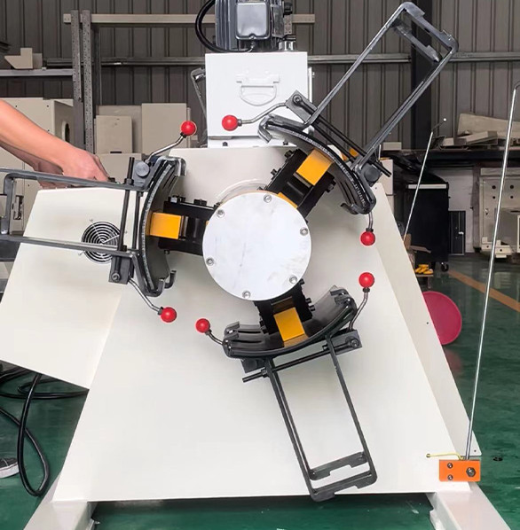
A shelving plant near Ningbo ran the same perforated coil for six years without a problem. Then a new die with a longer feed length went in, and every part came up 0.3 mm short.
The servo was blamed first, then the encoder, then the drive. The fault was none of them. It was where the feed rolls happened to sit on the hole pattern.
This is what the plant found, and the three settings that changed when a NC servo feeder was set up to feed perforated strip.

The Coil That Would Not Feed Straight
The material was 1.5 mm SPCC, 300 mm wide, punched with 2 mm holes on a 12 mm pitch. Open area was close to 22 percent.
The old die needed a 95 mm feed at 140 SPM and the line held ±0.05 mm for years. The new die needed 180 mm at 120 SPM, and the same line drifted to ±0.35 mm.
The drift was not random. It repeated within a coil and shifted between coils, which is the signature of a mechanical cause rather than an electrical one.
What the log showed. Feed length was short on roughly three strokes in ten, and always short, never long. A control or encoder fault usually produces scatter in both directions.
Short and repeatable pointed to slip. The strip was advancing less than commanded, which means the rolls lost grip for part of the stroke.
Chasing the Cause Past the Servo
The plant started where most do: with the drive. Torque was raised, then acceleration was reduced, then the encoder was swapped. Nothing moved the number.
Step one: mark the strip. A paint line across the strip before the feed rolls showed the strip slipping against the roll surface, not inside the roll gap.
Step two: count the contact. The feed rolls were 180 mm wide on a 300 mm strip, and the hole pattern ran in rows. At certain feed positions the roll sat almost entirely over open area.
Step three: measure grip over the full stroke. Effective contact varied from about 85 percent to under 50 percent as the pattern moved through the roll gap. Grip followed it.
The mechanism is simple once it is visible. A perforated strip has less material under the roll, so friction area drops, and friction is what moves the strip.
Why the pattern moves under the roll. The roll sits at a fixed position while the strip advances. Each stroke therefore brings a different section of the hole pattern into the roll gap.
On a 12 mm pitch and a 180 mm feed, fifteen rows of holes pass the roll in a single stroke. Grip changes with every one of them.
| Adjustment | Original Setting | Final Setting | Where It Costs You |
|---|---|---|---|
| Roll width | 180 mm | 280 mm | Wider rolls need more force and a heavier housing; capital cost rises with roll width |
| Roll position over the pattern | Centred on the strip | Offset to the solid edge bands | Limits later flexibility: a different pattern needs a new roll position |
| Feed acceleration | 18 m/s² | 11 m/s² | Slower acceleration cuts the maximum stroke rate, so throughput falls |
| Roll surface | Smooth chrome | Coarse-grit coated | More grip, but a higher risk of marking pre-painted or coated stock |
| Back tension | Free loop | Light controlled drag | Adds a payoff control loop that has to be tuned for every new coil |
Not every row was needed. The plant changed roll width, roll position and acceleration, and left the roll surface alone because the parts are painted after stamping.
Two rows were left alone on purpose. A coarse roll surface would have marked the parts, and adding controlled drag would have solved a problem the plant did not have.
That is the discipline the case illustrates. Change the setting that removes the cause, and leave the settings that only trade one symptom for a different one.
Three Changes That Settled the Feed
Three changes, one afternoon of setup, and no new machine. Feed length settled at ±0.08 mm on the same material.
Roll width. Going from 180 mm to 280 mm raised contact enough to cover the hole rows without depending on pattern position.
Roll position. Moving the rolls outboard onto the solid edge bands put them permanently over solid material, which is the single biggest contributor to the result.
Acceleration. Dropping from 18 m/s² to 11 m/s² removed the brief slip at the start of each feed. The die runs at 120 SPM, so the slower ramp costs nothing here.
The trade is real, though. The line now feeds 300 mm perforated strip well and would need re-setting for a 150 mm pattern, because the roll position is tuned to one pattern geometry.
What the change actually cost. Two days of production time for the roll swap and the trials, plus the price of a wider roll set. The servo drive, the encoder and the control software were all left untouched.
The plant also gained something it had not asked for. Feed length now holds on the second pattern it runs, because the wider rolls cover both hole layouts on that line.
- Perforated strip feeds best when the rolls run on solid edge bands, not on the pattern.
- Feed length that is short and repeatable is a grip problem. Scatter in both directions is a control problem.
- Longer feed lengths expose grip problems that short feeds hide, because the strip spends longer under the roll.
FANTY's engineering team, 80+ engineers across a 45,000 m² plant, sees this pattern most often on shelving, filter frame and motor housing work, where open area is high and feed lengths are long.
The feed units used on those jobs are listed on the press line equipment range page.
What a Perforated Coil Will Not Tolerate
The setup above works, and it has boundaries that are worth stating before someone tries to copy it onto a different job.
High open area defeats it. Above roughly 35 percent open area there may be no continuous solid band wide enough for the rolls to grip. At that point the material needs a different feed strategy.
Very long feeds make it worse. The longer the feed, the more pattern the strip passes under the rolls in a single stroke.
Beyond about 250 mm on a 12 mm pitch, grip variation returns even with the best roll position.
Coated stock is a separate problem. A coarse roll surface that fixes grip on bare steel will mark a pre-painted or galvanised strip. Do not carry the surface change across without testing a full coil.
- Below about 20 mm of solid band per edge, the rolls have nowhere reliable to sit.
- Open area above roughly 35 percent removes the solid bands entirely on most patterns.
- Hole rows running at an angle to the strip defeat edge-band positioning, because the band width changes along the coil.
One more caution. A feed log that looks good for twenty strokes proves very little on perforated strip, because grip varies with pattern position over a full coil.
How to Test the Setup Before You Release It
Perforated coil needs a longer acceptance run than plain strip, because the pattern moves through the rolls as the coil unwinds.
Run at least three full coils. The outer wraps, the middle and the core all behave differently. A short run tends to pass on the outer wraps and fail near the core.
Log the feed length per stroke. Not the average. The distribution is what tells you whether slip is present, and a short-and-repeatable tail is the tell.
Check the part, not just the feed. A 0.08 mm feed variation can still produce a burr or a short flange at the die. Measure the finished feature, not the commanded length.
Repeat on the second coil supplier. Hole pattern position varies slightly between coil suppliers, and a setup tuned to one mill's pattern may not hold on another's.
Watch the last two metres closely. The coil core behaves differently from the rest, because strip curvature is highest there and the payoff radius is smallest.
Keep the worst parts. Cut and store the parts from the position that gave the largest error. They are the reference the next die change is measured against.
Does a 2 mm hole pattern really change feed length?
Yes, once open area passes about 15 percent and the feed length is long. Below 15 percent open area on a short feed, most lines show no measurable effect.
How much contact do perforated feed rolls need, 60 or 90 percent?
Aim to keep effective contact above 80 percent through the whole stroke. Below about 60 percent, slip becomes likely as the pattern moves through the roll gap.
Does 30 percent open area make a coil unfedable?
Not on its own. It becomes a problem when the solid edge bands are narrower than the feed rolls. Below roughly 20 mm of solid band per side, expect to redesign the feed.
How many strokes should an acceptance run cover, 200 or 2,000?
At least 2,000, spread over three coils. Pattern position repeats over a coil circumference, so a 200-stroke run can easily miss the worst position.
Where to go next
Grip and slip sit at the centre of the line's feed accuracy budget, alongside loop control, lateral position and pilot release. The full budget from the payoff to the die is set out in the same cluster.