Which NC Servo Feeder Setup Suits Pre-Painted Panels?
- Share
- publisher
- David Park - Senior Stamping Engineer, FANTY Machinery
- Issue Time
- Sep 18,2026
Summary
Painted strip is the least forgiving material a press line runs, and the feed setup decides most of the reject rate. Three configurations are compared on marking, scuffing and edge damage, with the thickness and gloss limits where each one stops being the right choice.
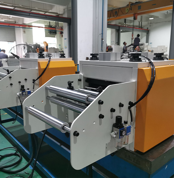
A pre-painted appliance panel is the least forgiving strip a press line will ever run. The coating is 18–25 µm of polyester or PVDF over a 0.4–0.8 mm substrate, and every place the strip touches a roll is a place the finish can be marked, burnished or cracked. When a plant tells me their reject rate on painted panels is 6%, the NC servo feeder setup is usually the first thing I look at — not the die.
There are three ways to feed a painted panel line, and they are not interchangeable. This article compares them on surface quality, cycle time and cost, then sets out where each one stops working. For the machine-level specification behind the numbers, the product range lists the standard feed roll and roll-lift configurations.
Why Painted Coil Punishes the Feed Rolls
Three things happen to painted strip between the decoiler and the die, and all three are mechanical.
First, coating is softer than steel. A polyurethane roll running at the same pressure as a steel roll still leaves a contact band, and if the strip is fed while the press is closing, that band becomes a visible scuff on the finished panel. Second, paint has almost no tolerance for shear. A roll that slips by even 0.3 mm on painted strip does not just lose position — it scrapes the surface, and the mark survives painting, forming and assembly. Third, the coating changes the friction coefficient. Bare cold-rolled steel sits around 0.12–0.15 with light oil; painted strip can drop to 0.08–0.10, which means the same roll pressure produces less grip exactly when you need more.
That last point is the reason a setup that holds ±0.05 mm on bare SPCC at 200 strokes per minute can drift 0.4 mm on painted stock. Nothing has worn out. The friction is simply lower, and the feeder's margin was thinner than the specification suggested.
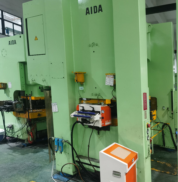
Three Ways to Feed a Painted Panel Line
The three candidates below all exist in production. They differ in how many times the strip is gripped, how much pressure each grip applies, and how much of the coating is left afterwards.
| Setup | How the strip is gripped | Coating risk | Relative cost | Best fit |
|---|---|---|---|---|
| Standard NC servo feeder, steel rolls | One pair of rolls, full pressure, gripped for the whole index | High — scuffing and roll banding | Baseline | Bare or lightly oiled strip, non-visible parts |
| NC servo feeder with urethane rolls and a pilot release | One pair of urethane rolls, reduced pressure, released during the press stroke | Low — contact time cut to the index only | Baseline + 6–11% | Visible painted panels, 0.4–1.0 mm |
| NC servo feeder with a hold-down and a film-lined guide path | Urethane rolls plus a full-length hold-down that carries the strip between grips | Very low — no unsupported span, no flapping | Baseline + 14–20% | High-gloss or textured coatings, thin gauge, high visual standard |
The middle option is the one most plants should be running and the one most plants are not. A pilot release that lifts the upper roll during the press stroke is a small mechanical addition, and it removes the entire class of damage that happens while the strip is stationary under load. On a 0.6 mm painted panel job running 120 strokes per minute, the roll is in contact with any given point of strip for roughly 0.35 seconds instead of 0.5 — the difference between a mark you can measure and a mark you can see.
The third option adds a hold-down that spans the distance between the feeder and the die entry. Its value is not extra grip; it is eliminating the unsupported span where thin painted strip sags, flaps and touches things it should not. Below 0.5 mm on a 1,200 mm width, that span is the main source of surface defects, and no amount of roll tuning fixes it.
What Each Setup Leaves Behind on the Panel
Surface damage on painted panels comes in four recognisable forms, and the setup determines which ones you get.
Roll banding is a continuous, evenly spaced line along the strip where the feed roll contacts. It is pressure and hardness, and urethane rolls at 60–70 Shore A remove most of it. It almost always appears on the top face because that is where the driven roll usually sits.
Scuff marks are short, directional scratches. They come from slip — the roll moving relative to the strip during the index. Slip on painted strip is nearly always a friction problem rather than a pressure problem, which is why raising roll pressure makes scuffing worse rather than better.
Coating crazing appears at the bend radii after forming. It is not caused by the feeder directly, but a feeder that over-straightens or pulls the strip through a tight entry angle pre-stresses the coating and makes the forming cracks worse. If crazing appears only on parts fed from one direction, the entry geometry is the suspect.
Edge marking runs along the strip edges where side guides rub. It is the easiest to fix and the most often ignored: a guide that contacts a painted edge at 0.5 mm interference will mark the full coil length. Set guides to 0.2–0.5 mm clearance per side and accept the small amount of lateral float.
Cycle Time and What Each Setup Costs Per Hour
The three setups differ in index time by more than most people expect. Urethane rolls can be run at slightly higher acceleration because they conform to the strip instead of biting it, and a pilot release shortens the press dwell requirement by letting the roll lift earlier.
On a 1,200 mm wide, 0.6 mm painted panel job, typical figures look like this: steel rolls and no pilot release, 105–115 strokes per minute; urethane rolls with pilot release, 118–128 strokes per minute; hold-down plus pilot release, 120–130 strokes per minute. The gain from the middle option is real — around 10% more parts per hour — but it is not the reason to buy it. The reason is the reject rate.
Run the arithmetic on rejects instead of speed. A plant producing 4,200 painted panels per shift with a 6% surface reject rate loses 252 panels. Every one of those panels has already absorbed the coil cost, the press time and the labour. Cutting the reject rate to 2% recovers 168 panels per shift, and on a part that sells at USD 4–7 that is USD 670–1,180 of recovered value per shift — which pays for a urethane roll set and a pilot release in a matter of weeks, before any of the speed gain is counted.
Where Each Setup Stops Working
- Steel rolls above 1.2 mm painted stock. Not because of grip — because the pressure needed to prevent slip at that thickness is enough to mark the coating every time. If the part is visible, this configuration is the wrong choice regardless of how the rolls are ground.
- Urethane rolls above roughly 2.0 mm. The roll deforms under the load needed to drive heavier strip, and the effective contact patch grows until it behaves like a flat pad. Thickness capability drops even though the machine is rated higher.
- Pilot release below about 60 strokes per minute. The timing window becomes long enough that the roll lift is no longer the limiting factor, so the mechanism adds cost without adding quality. On a slow line, spend the money on the hold-down instead.
- Hold-downs on strip narrower than 300 mm. Below that width the strip has enough stiffness for its own weight and the hold-down mostly adds a surface to rub against. Guide the edges instead.
- Any of the three with textured or embossed coating. Embossed finishes are unforgiving in a different way: they hold dirt and they cannot be polished out. For those, feed on a protective film and strip it after forming, and treat the feeder as a film-handling device.
What I Would Specify for a 0.6 mm Appliance Panel Job
Given a 0.6 mm pre-painted panel, 1,150 mm wide, 4,000 panels per shift, visible on both faces, this is the specification I would put on the order.
Feed rolls in urethane at 65 Shore A, driven top and bottom, with a pilot release tied to the press crank angle and set to lift the upper roll 6–8 mm clear. A hold-down shoe across the full strip width between the feeder and the die entry, set to 0.5 mm clearance so it carries the strip without pressing it. Side guides with 0.3 mm clearance per side, hard-chromed and radiused rather than square-edged. Roll pressure set by a calibrated dial gauge, not by feel, and recorded per die in the feeder's recipe memory so a changeover does not start from scratch.
Two numbers to put in the acceptance test: feeding accuracy of ±0.05 mm on 0.6 mm painted stock at 120 strokes per minute, measured over a 500-part run, and a surface reject rate below 2% on a full coil. Both are measurable, and both are the numbers that decide whether the specification was right.
FANTY builds these lines on a 45,000 m² floor with 370 people, and the painted-panel configuration is one of the more common requests from appliance and HVAC customers. The point I make to every one of them is the same: on painted stock, buy the handling, not the horsepower. A larger feeder motor will not fix a scuff mark.
One caution about the reject-rate target. If your die is producing the crazing rather than the feeder, no feed configuration will bring you under 2%, and you will spend money in the wrong place. Run one coil with the roll pressure reduced to the minimum that still holds position and look at where the defects fall on the panel. If they cluster at a bend radius, the die or the material is the cause; if they are spread along the strip, the feed path is.
Can I run painted strip on the steel rolls I already have?
For non-visible parts, yes, and many plants do. Reduce roll pressure to the minimum that holds position, reduce the feed speed by 15–20%, and inspect the first 50 parts of every coil. The moment the part becomes visible to the end customer, switch to urethane — the pressure that prevents slip on steel rolls is above the threshold that marks paint.
Does a pilot release wear out faster on painted lines?
The mechanism cycles with the press, so at 120 strokes per minute it sees 57,600 cycles per shift. That is normal service for a properly sized cam or pneumatic release, but the guide pins and the lift springs should be on a 2,000-hour inspection interval rather than the usual annual one.
How do I set roll pressure without a gauge?
You cannot, reliably, and this is where most painted-panel problems start. Fit a pressure gauge to the upper roll cylinder, record the value per die in the recipe, and set the roll to the lowest pressure that produces no slip on a 30-part test. If you have no gauge, borrow a portable hydraulic test gauge for one day and build the table — it takes an afternoon and removes the guesswork permanently.
Will urethane rolls change my feed accuracy?
They can, and usually in the direction you want. Urethane conforms to the strip, so the contact patch is larger and grip is more consistent across the width. The trade-off is that urethane creeps slightly under sustained load, so a feeder with a long index time and a slow release should be checked for position drift over a 200-part run before the acceptance test is signed.
What film should I use if the coating is textured?
A 50–80 µm polyethylene film applied at the coating line is the usual answer, and it needs to survive the feeder without being dragged. Set the feed rolls to grip through the film rather than on bare paint, keep the film under slight tension, and strip it after forming. Do not run textured coil bare and hope — the defect rate on embossed finishes without film runs several times higher.
Feeding Painted Coil? Let's Get the Roll Configuration Right First
Tell us your coating type, thickness and panel size. We will recommend the feed roll material, the release configuration and the guide clearances, and quote the line as a package rather than as a machine.
Discuss Your Painted Panel Line