Which Part of an NC Straightener Feeder Limits Accuracy?
- Share
- publisher
- David Park - Senior Stamping Engineer, FANTY Machinery
- Issue Time
- Sep 11,2026
Summary
An accuracy budget for a 3-in-1 machine: how much error the decoiler, straightener and feeder sections each contribute, which one usually dominates, and how to isolate each in one shift.
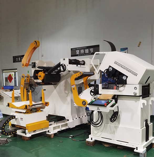
When a stamped part drifts out of tolerance, the conversation usually goes straight to the die. That is the expensive place to look. A 3-in-1 machine has three sections — decoiler, straightener, feeder — and each one contributes a measurable share of the total positioning error. Finding which share dominates tells you where to spend your time.
Below is how we break down an accuracy budget on an NC Straightener Feeder, based on measurements taken across machines running from 0.4 mm to 6 mm strip.
Accuracy Is an Error Budget, Not a Single Number
Every brochure quotes a tolerance. Almost none of them explain how that tolerance is composed. The total error in strip position at the die entry is the sum of several independent contributions, and treating it as one lump makes diagnosis impossible.
The practical breakdown has five terms: pay-off tension variation from the decoiler, leveler roll gap repeatability, strip slip at the feed rolls, mechanical drift in the feed carriage, and control resolution plus timing. The first two are usually small. The last three carry most of the total, and two of them belong to the feeder section.
The Feeder Section: Usually the Dominant Term
Feed rolls are where the machine commits to a length. Everything upstream can be perfect and still be wasted if the roll pair slips by 0.15 mm during acceleration.
Slip is not a constant. It varies with lubricant film thickness, roll surface condition, strip surface condition and acceleration rate. On a line running 180 SPM, a 0.1 mm slip during the acceleration phase translates into a 0.1 mm die-station error, which compounds across a progressive die. By station five, a 0.1 mm feed error can produce a 0.5 mm feature offset because the accumulated error is no longer shared between stations.
What makes slip worse over a shift
Two things change as the machine runs. Roll surfaces accumulate lubricant and metallic debris, which lowers the friction coefficient. And hydraulic oil warms, which changes roll pressure slightly if the system uses hydraulic clamping. Both effects push accuracy in the same direction, which is why the end of a shift is often worse than the start.
What actually improves it
Grip per unit of pressure, not more pressure. Hardened roll surfaces with a controlled roughness, adequate roll diameter to spread contact, and a motion profile that keeps peak acceleration within the friction budget. On a machine designed this way, ±0.05 mm holds at 200 SPM through a full shift rather than for the first hour.
The Straightener Section: Flatness Feeds Back into Length
Leveling looks like a flatness function, and it is. But residual curvature also changes the effective path length between the leveler exit and the die. A strip that leaves the leveler with a small upward bow is slightly longer along its neutral axis than a perfectly flat strip of the same nominal length.
This is why operators sometimes see feed length drift after adjusting the leveler. The feed rolls are not at fault; the geometry between the two stations changed. The effect is small — typically under 0.03 mm on 1 mm strip — but it is systematic, not random, so it will show as a consistent offset rather than scatter.
Roll gap repeatability
If your leveler uses manual screw adjustment, the gap you set on Monday is not necessarily the gap on Friday. Digital gap indication with a repeatable reference does more for process stability than a tighter nominal tolerance, because it makes the setting reproducible between shifts and operators.
The Decoiler Section: Small, but It Sets the Baseline
The decoiler does not position the strip in the die, so its direct contribution to length error is the smallest of the three. What it controls is back-tension, and back-tension is the input condition for everything downstream.
A pay-off control that hunts produces a slow tension oscillation. The feed rolls see a varying resistance, and the servo compensates by drawing more or less current — which changes the small elastic stretch of the strip between the rolls and the die. The result is a periodic length variation that repeats at the pay-off cycle frequency rather than at the press frequency. That signature is the giveaway.
The countermeasure is a decoiler control with adequate response and, where the loop is long, a dancer or an ultrasonic loop sensor. On a 3-in-1 decoiler straightener feeder with an integrated loop control, this problem is designed out rather than tuned out.

Typical Contributions Measured in the Field
The table below shows what we normally see on a well-set-up line running 1.5 mm mild steel at 180 SPM with a 300 mm feed length. Use it to decide where to look first when tolerance drifts.
| Error source | Section | Typical contribution | Behaviour |
|---|---|---|---|
| Pay-off tension variation | Decoiler | 0.01–0.04 mm | Periodic, follows pay-off cycle |
| Leveler gap repeatability | Straightener | 0.01–0.03 mm | Systematic offset, changes between shifts |
| Residual curvature path length | Straightener | 0.01–0.03 mm | Systematic, changes with leveler setting |
| Roll slip during acceleration | Feeder | 0.05–0.15 mm | Random to semi-random, grows through shift |
| Feed carriage mechanical drift | Feeder | 0.02–0.06 mm | Slow trend, temperature linked |
| Control resolution and timing | Feeder | 0.01–0.02 mm | Random, very small with modern drives |
| Strip thickness scatter | Incoming material | 0.02–0.10 mm | Correlates with coil position |
Read the column of contributions and the answer is usually obvious. Roll slip and incoming material scatter dominate. Note that one of them is not a machine problem at all — which is why coil tolerance belongs in your incoming inspection, not in a maintenance ticket.
How to Separate the Three Contributions in One Shift
You do not need instrumentation beyond what the controller already provides. Run this sequence in order and each step isolates one section.
- Run with the decoiler in manual constant tension and the loop held steady. If scatter drops sharply, the pay-off control is your source
- Run at reduced acceleration with the same takt where possible. If accuracy improves, roll slip is the dominant term
- Log feed length for two hours without touching any setting. A downward or upward trend points at thermal drift in the carriage or the hydraulic system
- Change only the leveler gap by a known amount and watch whether feed length shifts. This isolates the flatness-to-length coupling
- Measure incoming strip thickness at five points across the width every 50 metres. Material scatter shows up as a correlation with coil position
- Repeat the whole sequence at the end of the shift. If the ranking of contributions changes, you have a wear or thermal problem rather than a design limit
FANTY has been building coil feeding equipment for 12 years and ships to more than 60 countries, and this diagnostic sequence comes from support cases where the customer was certain the die was at fault. In roughly seven out of ten cases the feeder section was carrying most of the error, and roll grip was the specific cause.
Questions About Where Accuracy Comes From
Does a 3-in-1 design improve accuracy compared with separate machines?
It removes one class of error, not all of them. An integrated machine eliminates the free strip length and the separate guide alignment between the straightener and the feeder, so the flatness-to-length coupling and the guide drag variation both shrink. Roll slip and control resolution are unchanged — those depend on the feeder design itself.
Why is accuracy better in the morning than at the end of the shift?
Two mechanisms. Roll surfaces pick up lubricant and debris, lowering the friction coefficient, and hydraulic oil warms, shifting clamping pressure. Both reduce grip. If your scrap curve rises through the day, cleaning the feed rolls at mid-shift is a cheap first test.
Can I tighten tolerance by slowing the line down?
Yes, but it is a blunt instrument. Reducing speed lowers acceleration, which lowers slip. It also lowers your output. Before accepting a slower line, check whether the motion profile can be reshaped to reduce peak acceleration without extending the total feed time much.
How much does incoming coil tolerance affect final part accuracy?
More than most buyers expect. Thickness scatter of 0.08 mm across a coil changes both the leveler setting requirement and the effective feed length. On a 300 mm feed that can account for a meaningful share of your total tolerance band, and no machine adjustment can remove it.
Chasing Tolerance Drift on Your Line?
Send us your strip data, feed length and current accuracy readings. Our engineers will tell you which section is most likely setting your limit, and what to change first.
Request an Accuracy Review