Why Do Thin Laminations Slip in a Straightener Feeder?
- Share
- publisher
- David Park - Senior Stamping Engineer, FANTY Machinery
- Issue Time
- Oct 12,2026
Summary
Thin silicon steel does not slip for one reason, it slips for five, and they leave different signatures. This article separates slip between the rolls, after the rolls and before the rolls, then ranks the causes by what you can measure. It covers oil film, glazed rolls, pilot release timing and die drag, and explains why a machine rated to 6 mm behaves differently at 0.5 mm.
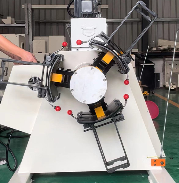
A motor lamination line running 0.5 mm silicon steel does not fail loudly. It drifts a tenth of a millimetre, then a quarter, and the scrap bin fills up over a shift.
Thin-gauge strip is where coil feeding stops being forgiving, because the material has almost no stiffness to push back against the rolls.
This article ranks the causes of slip on a NC straightener feeder by how often they turn up, and names the cases where the fault is not in the feeder at all.

What Actually Happens When Thin Strip Slips
Slip is not one event. It is a short loss of grip somewhere between the feed rolls and the die, and it leaves a different signature depending on where it happens.
Between the rolls. The strip moves less than commanded. Parts come out short by a consistent amount, and the error repeats stroke after stroke.
After the rolls. The strip is released correctly but drags in the die. Parts vary randomly, and the error grows as the die heats up.
Before the rolls. The loop goes tight, the feeder pulls against a loaded coil, and the error appears only at certain coil diameters.
Three signatures, three different fixes. Separating them takes twenty minutes with a dial indicator and saves a week of adjusting the wrong screw.

Check Roll Pressure Last, Not First
Roll pressure is the easiest thing to change, so it gets changed first. On thin stock it is also the least likely cause.
Start with the oil film. A heavier lubricant that works on 2 mm mild steel can float a 0.5 mm lamination clean off the roll surface. Wipe a test strip and watch the error change.
Then check roll condition. Glazed or polished rolls lose bite long before they lose flatness. A roll that looks perfect under a workshop light can still be polished smooth.
Only then adjust pressure. Adding pressure to thin strip mostly adds marking and roll deflection, not grip, and it hides the real cause for another month.
The order matters because each step changes what the next step measures. Adjust pressure first and every later observation is contaminated.
Each signature points at a different first action, and writing the reading down at the same time is what makes the next diagnosis faster.
| Signature on the Part | First Action | What to Record | Where It Misleads |
|---|---|---|---|
| Consistently short | Check roll grip and oil film | Error across 50 strokes | A constant offset can also be a wrong feed length in the program |
| Randomly short | Check die drag with the die closed | Die temperature | Random error looks electrical and almost never is |
| Error at certain coil diameters | Check loop and payoff tension | Coil diameter at failure | Blamed on the feeder because the feeder is the visible machine |
| Error only at high stroke rate | Check pilot release timing | Crank angle of release | Passes every slow test, so it survives into production |
| Cause | How to Confirm It | Typical Reading | Where It Misleads You |
|---|---|---|---|
| Oil film too heavy | Wipe strip dry on a test run | Error drops 0.05–0.15 mm | Looks like a pressure problem because wiping also changes friction |
| Glazed feed rolls | Surface roughness check against a new roll | Ra falls below 0.4 µm | A polished roll still measures round and still passes a visual check |
| Excess roll pressure | Reduce pressure in steps and watch the error | Error flat or worse | Short-term improvement as marking flattens the strip into the roll |
| Pilot release too early | Strobe or high-speed camera on the pilot | Release before roll close | Only shows up at high stroke rates, so it is missed on a slow test |
| Die drag | Feed with the die open, then closed | Error appears only with the die closed | Blamed on the feeder because the feeder is the visible machine |
Where Thin Material Punishes a Big Machine
A line rated to 6 mm can physically accept 0.5 mm strip. That does not mean it will feed it well.
Roll diameter works against you. Large rolls bend thin strip over a long arc, and the work per pass drops. The straightener can only flatten what it actually bends.
Gap resolution becomes the limit. If the finest reliable gap adjustment is 0.05 mm, setting a gap for 0.5 mm stock is a fifth of the available resolution.
Inertia is not the problem. The rolls are heavy, but the strip is light. On thin stock the feeder rarely runs out of torque; it runs out of grip.
That is the practical reason a machine sized for heavy gauge needs its lower range treated as a different operating regime, with its own settings and its own record.
Our coil line product range lists the thickness window each frame is built around.
When Slip Is Not a Feeding Problem
Roughly a third of the thin-gauge slip cases we see on site are traced to something other than the feeder. Three of them are worth ruling out early.
Coil set memory. Silicon steel holds a curve from the coil. If the straightener does not remove it, the strip enters the die off-centre and drags on one side.
Thickness variation along the coil. A coil that runs 0.48 mm at the outside and 0.52 mm at the core changes the required gap by 8 %. One setting cannot serve both ends.
Pilot and pilot release timing. If the pilot enters before the strip is fully released, the pin straightens the strip and the feed is recorded as accurate while the part is not.
The honest limit here is measurement. A feeder error and a die error can produce the same part defect, and no amount of adjustment on the feeder will separate them. Measure the strip position, not the part.
The Settings Worth Recording for Thin Stock
A lamination line usually runs the same few materials for years, so a written setup record is worth more than any single adjustment.
- Roll pressure for each material and thickness, recorded as a gauge reading rather than a screw turn.
- Straightener gap and penetration, plus the roll number where the setting was proved.
- Pilot release timing in degrees of crank angle, not in milliseconds.
- Loop depth at the working stroke rate, because the same loop behaves differently at 120 and at 200 SPM.
- Lubricant grade and concentration, including any change of supplier.
Record the readings, not the adjustments. A screw position means nothing on a machine with a different lead, and most plants eventually run more than one frame size.
How to Prove the Fix Actually Held
A slip fix that holds for one coil proves nothing. Run a short acceptance test before you release the line to production.
Warm the die first. Twenty minutes of running brings the die to temperature, and die drag changes with heat.
Run at production rate. If the line runs at 200 SPM, test at 200 SPM. A fault that only appears at speed will hide in a slow test.
Measure the strip, not the part. Take fifty consecutive readings at the feed point and hold the spread to ±0.05 mm, which is the accuracy these lines are built to.
Repeat at the coil core. The last third of the coil is where thickness and coil set change most, so test there as well as at the outside wrap.
If the error returns at the coil core but not at the outside wrap, you are looking at material variation rather than a feeder fault, and the answer is a different gap strategy, not a different machine.
Feed accuracy across the whole line, from the decoiler through to the die, is broken down item by item in the coil line guide library.
The same grip problem behaves differently when the gauge climbs, which is why 6 mm heavy-gauge feeding follows almost the opposite rulebook.
At what thickness below 0.8 mm does a straightener feeder start to slip?
Slip risk climbs sharply below about 0.8 mm on a machine sized for 3 mm and above. The material has less stiffness to push back, so oil film and roll surface start to dominate.
How much thickness variation can one gap setting absorb on 0.5 mm strip?
Treat 5 % as the practical limit. On 0.5 mm stock that is 0.025 mm, so a coil running from 0.48 to 0.52 mm needs either a compromise gap or a two-pass strategy.
Does higher roll pressure always improve grip?
No. Above a threshold it adds marking and roll deflection instead of grip. On thin stock, most plants reach that threshold well before the pressure gauge suggests they should.
How long should a slip fix be tested before release?
Run at least three full coils at production rate, including the core of each coil. Anything shorter tends to pass on the outside wrap and fail later in the shift.
Where to go next
Thin-gauge slip is one layer of the feed accuracy problem. The full error budget from decoiler to die, and how each item trades against cost, sits in the same cluster.