Can a 3-in-1 Straightener Feeder Run Two Gauges?
- Share
- publisher
- David Park - Senior Stamping Engineer, FANTY Machinery
- Issue Time
- Nov 6,2026
Summary
A gauge change on a 3-in-1 line takes thirty-five minutes against eight for a die change, and most of the extra time goes on two settings that look right and are not. The article runs through six checks in order, explains why gap reads in millimetres while penetration scales with the square root of thickness, and pairs back tension with loop height. It ends with the first-piece measurements that catch a leftover setting.
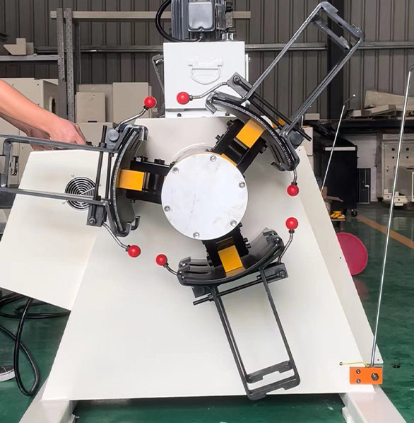
The die change takes eight minutes. The gauge change that follows it takes thirty-five, and most of that time is spent on two settings that look right and are not.
Running 0.8 mm in the morning and 2.0 mm after lunch is routine work for a 3-in-1 straightener feeder.
It works provided the operator resets the parameters that scale with thickness, rather than the ones that merely look different.
These are the six checks we walk through with a new crew, in the order that avoids scrapping the first twenty blanks.
Six Checks Between One Gauge and the Next
The sequence matters because each check depends on the one before it. Skip the gap and the intermesh setting is meaningless.
One: strip the line. Never change gauge with the strip threaded. The old strip holds the rolls open at the previous setting and the new gap will be wrong by whatever the strip thickness was.
Two: set the roll gap. Mechanical gap first, then the intermesh adjustment. On a 3-in-1 the two are separate controls and operators routinely set one and assume the other.
Three: reset back tension. Tension scales with the cross-section, so a 2.0 mm job needs roughly 2.5 times the tension of the 0.8 mm job on the same width.
Four: reset loop height. Thicker strip tolerates a shorter free loop because it resists buckling, and a loop set for thin stock will drag on a thick job.
Five: reset the feed length and pilot release timing. Feed length may be identical; the release window rarely is, because the strip takes longer to settle on a heavier gauge.
Six: run three blanks and measure. Not one. The first blank off a cold line is never representative.
Roll Gap: The Setting That Carries Over Wrong
Gap is where the arithmetic is simple and the practice is not.
For 0.8 mm cold-rolled strip, a working gap is about 0.62 mm, which leaves roughly 0.18 mm of penetration per side on the upper and lower roll sets.
For 2.0 mm the gap moves to about 1.55 mm with 0.22 mm of penetration.
The trap is that the gap adjuster reads in millimetres of roll separation, not in penetration.
An operator who moves the dial from 0.62 to 1.55 has changed the gap correctly and changed the penetration by only 0.04 mm.
That is usually the right direction, because penetration does not scale linearly with thickness.
It scales closer to the square root, which is why a 2.5× thickness change asks for a 1.2× penetration change rather than 2.5×.
The second trap is thermal. A line that has run 2.0 mm for four hours holds heat in the roll stack, and the first 0.8 mm job afterwards will run 0.03 to 0.05 mm tight until the rolls cool.
Gap range per frame size is listed on the machine specification pages, and it is worth checking before a job is quoted rather than after the die arrives.
The same arithmetic holds on any NC straightener feeder with a mechanical gap adjuster, whether the head carries 5 rolls or 9.
Intermesh and Roll Count on the Second Gauge
Roll count does not change between the two jobs. The number of rolls is a property of the head, and a 7-roll head stays a 7-roll head.
What changes is how much work each roll does. On 2.0 mm at 340 MPa the bending curvature per roll has to rise to reach the yield surface through the thickness, and the intermesh setting carries that load.
On a 7-roll head running 2.0 mm, intermesh typically sits at 80 to 90 percent of the maximum the frame allows.
On 0.8 mm the same head runs at 35 to 45 percent, because full intermesh on thin strip puts a permanent curl into the material rather than removing one.
That single ratio explains most of the flatness complaints that follow a gauge change. The operator sets intermesh by feel, the feel was calibrated on 2.0 mm, and the 0.8 mm job comes off the line with edge wave.
Back Tension and Loop Have to Move Together
These two are set as a pair or not at all. Changing one without the other produces a length error that looks like a feed fault.
| Parameter | 0.8 mm setting | 2.0 mm setting | Where it bites if left alone |
|---|---|---|---|
| Back tension | Around 1.1 kN on 1,250 mm width | Around 2.7 kN on the same width | Too little tension on 2.0 mm lets the strip wander and the coil telescope |
| Loop height | 250 to 300 mm | 150 to 200 mm | A thin-stock loop on thick strip drags on the guide and shows as a length shortfall |
| Feed roll pressure | Low, marking-limited | Higher, slip-limited | Thin-stock pressure on 2.0 mm slips within 200 strokes |
| Pilot release window | Earlier, strip settles fast | Later by 8 to 12 degrees of crank | Early release on thick strip pulls the part off location |
The tension figures are for a 1,250 mm width and will scale with your strip.
What does not scale is the ratio: 2.5 times the cross-section needs roughly 2.5 times the tension, and a line that keeps the thin-stock setting will run the thick job with the strip floating.
The First-Piece Check That Catches Everything Else
Three blanks, measured properly, will find any of the six settings that was left behind.
- Length, on all three. A drift across three blanks means slip or tension, not drive tuning.
- Flatness on a surface table. Edge wave points at intermesh; centre buckle points at gap.
- Curl over a 500 mm span. More than 3 mm of curl on 0.8 mm means the intermesh is still set for the thick job.
- Surface under a loupe. Roll marks that were invisible on 2.0 mm become visible on 0.8 mm at the same pressure.
Flatness is the check most often argued about, because the spec is usually written as a number per metre without saying which direction.
The full set of relationships between roll count, pitch, gap and penetration is in our 3-in-1 decoiler straightener feeder reference, including how to read a spec that names only one direction.

What Carries Over Cleanly, and What Only Looks Like It Does
Some settings genuinely do not need touching, and confusing them with the ones that do is how a changeover doubles in length.
Feed length carries over if the die is the same. The number is a property of the tool, not the strip, so a gauge change on one die keeps the same value.
Roll alignment does not need re-shimming for a gauge change. It is a frame property, and disturbing it to chase a flatness complaint is how a good alignment gets lost.
What only looks like it carries over is the pressure setting. The regulator number stays the same, the force does not, because the contact arc changes with thickness.
A 0.8 mm job run at the 2.0 mm regulator setting will mark; a 2.0 mm job run at the 0.8 mm setting will slip.
The line speed is the other false friend. A 3-in-1 rated at 200 SPM on 0.8 mm will not hold the same rate on 2.0 mm, and the derating is not linear.
Expect 90 to 110 SPM on the heavy gauge, and set the press to match rather than letting the line chase.
Two Gauges a Week Is a Different Decision
Frequency decides whether this is a procedure or a purchase.
At two gauge changes a week, a written card per die and a thirty-five minute changeover is the right answer. The cost is operator attention, and it is small.
At two a shift, the arithmetic changes.
Four changeovers a day at thirty-five minutes is over two hours of lost press time, which is where a second line or a cassette roll head starts to compete on cost rather than on convenience.
The middle case is the awkward one. One changeover a day, on a line that also runs three other dies, usually justifies a preset parameter set stored in the controller rather than any hardware.
Storing the six values per die removes most of the thirty-five minutes and none of the capital.
Our own builds store up to 40 parameter sets for exactly this reason, and the ±0.05 mm figure quoted for them assumes the stored set is recalled rather than retyped.
How long should a 0.8 mm to 2.0 mm changeover take?
Thirty to forty minutes with a written card and stored parameters, and closer to seventy if every value is set by hand. The gap and intermesh adjustments account for about half of it.
Does a 7-roll head handle 2.0 mm at 340 MPa?
Yes, at 90 to 110 SPM and with intermesh near 85 percent of frame maximum. A 5-roll head will struggle to remove coil set at that gauge, and a 9-roll head adds friction without adding flatness.
How much back tension does 2.0 mm need on 1,250 mm width?
About 2.7 kN, against roughly 1.1 kN for 0.8 mm on the same width. The ratio follows the cross-section, so a 1,000 mm width needs about 2.2 kN.
Why does the first 0.8 mm job after a heavy run come out tight?
Heat in the roll stack. The gap closes by 0.03 to 0.05 mm as the rolls cool, so the first twenty blanks run under gauge. Let the line idle for ten minutes or accept a short ramp.
Where to go next
Gauge changes sit on top of a flatness system that has to be right before the changeover procedure can help.
The roll-by-roll basis of that system, and how to read a flatness spec that only names one direction, is in the flatness reference.
Open the flatness setting guide