Can an NC Servo Feeder Run Narrow Strip Without Twisting?
- Share
- publisher
- David Park - Senior Stamping Engineer, FANTY Machinery
- Issue Time
- Sep 20,2026
Summary
Narrow strip has a fraction of the torsional stiffness of wide strip, so the same machine behaves differently. This is the five-step setup that keeps 60 mm strip tracking, what each failure mode costs in speed.
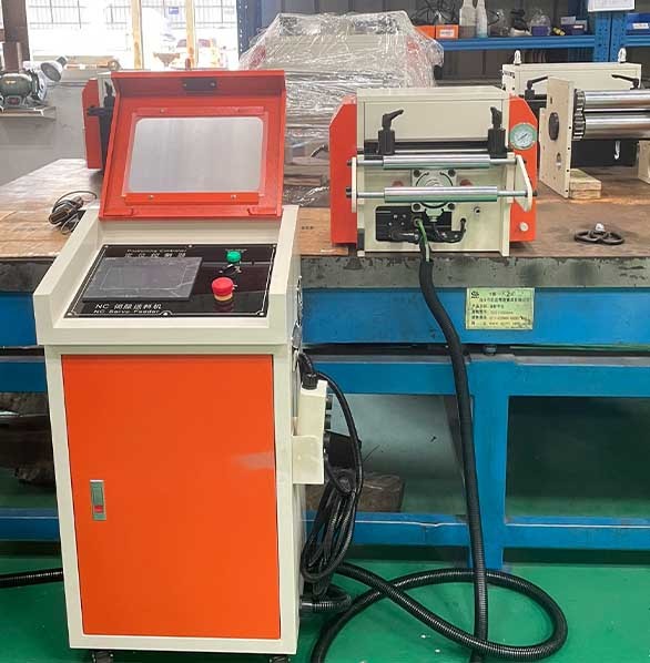
Set up a coil line for 300 mm strip and it behaves.
Set up the same line for 60 mm strip and the material starts rotating about its own axis between the rolls.
It wanders into the die at an angle, and the parts measure correctly at the pilot but are scrapped at the trim.
The machine has not changed. The strip has, and narrow strip is mechanically a different problem.
Torsional stiffness for a flat section scales roughly with width times thickness cubed, so cutting the width from 300 mm to 60 mm removes five sixths of the resistance to twist.
This is the setup sequence that works on narrow strip, the points where it has to be measured rather than felt, and the cases where no amount of setup will help.
The machine options are listed in our product range, and the measurement side of the same problem sits in the feed accuracy error budget from decoiler to die, part of our coil line knowledge base.
Why Narrow Strip Behaves Differently
Three effects scale with width, and they all get worse as the strip gets narrower. None of them are visible on a wide line.
Torsional stiffness collapses. For a flat section, the torsional constant is approximately one third of width times thickness cubed.
Halving the width halves the resistance to twist; halving the thickness cuts it by eight.
Camber becomes proportionally larger. Slitting leaves a bow in the strip that is measured in millimetres over metres, and that bow is roughly independent of width. On a 300 mm strip it is a small angle.
On a 60 mm strip it is the same absolute bow over a fifth of the width, so the tracking error grows.
Roll pressure cannot be uniform. Feed rolls are crowned or relieved for a working width.
A strip occupying the centre 60 mm of a 300 mm roll face sees only the middle of that profile, which is the flattest part — but the roll's own deflection under load is set by the machine, not by the strip.
The practical consequence: a machine rated at ±0.05 mm feeding accuracy for its full width range will not hold that on a 40 mm strip without the setup below. The rating describes the machine, not your strip.
The Five Setup Steps That Decide It
- Set roll pressure from a measured contact pattern, not by feel. Feed a short length of strip with carbon paper between the rolls and read the imprint. Narrow strip wants full-width contact at the lowest pressure that still grips. Aim for about 30–50% less pressure than the same machine would use on wide strip.
- Centre the strip on the roll face. Measure from each roll edge to the strip edge and make the two distances equal within 0.5 mm. Off-centre loading on a narrow strip puts the whole feed force through part of the roll face and produces a sideways component that shows up as wander.
- Shorten the unsupported span. The distance between the last roll and the die entry is where twist develops. On narrow strip, fit a guide tube or a support channel across that gap. Reducing the span from 600 mm to 300 mm typically removes more twist than any other single change.
- Use spring-loaded edge rollers, not fixed discs. Fixed discs constrain the strip at one point and induce twist the moment the strip is not perfectly straight. Spring rollers centre it while allowing the small lateral movement that camber demands.
- Slow the acceleration ramp. Twist is worst in the first 20 mm of a feed, when the strip's inertia is fighting the roll grip. Lengthen the ramp on an S-curve profile and accept the small cycle-time cost. This is the step most operators skip because it reduces the stroke rate.
Run the five in that order. Pressure comes first because it changes the contact geometry, and centring follows because it depends on pressure.
The span is third because it is the largest single lever, guides are fourth, and the ramp is last because it is the only step that trades speed for stability.
What Each Failure Looks Like and What It Costs
| What you see | What is causing it | The fix that works | Where the fix costs you |
|---|---|---|---|
| Strip rotates about its axis at the start of each feed | Acceleration too aggressive for the strip's torsional inertia | Lengthen the ramp on an S-curve profile | Cycle time. On a 180 mm feed this can cost 3–5% of strokes |
| Bright or rolled strip edge | Fixed disc guides pinching, or excessive roll pressure | Spring edge rollers, pressure set from a contact imprint | Grip margin. Lower pressure on oily strip means the roll coating has to do more work |
| Strip wanders into the die off-centre | Slit camber combined with too long a free span | Guide tube across the span, spring rollers at the entry | Changeover time on every width change, plus clearance tuning |
| Feed length drifts by 0.1 mm or more | Strip slipping on the rolls at low pressure | Higher-friction roll coating, or pressure raised to the point where the edge is still clean | Roll life. Higher friction coatings wear faster and are a consumable |
| Strip bows upward between the rolls | Roll pressure high relative to strip width, so the strip yields across its width | Reduce pressure; if grip is then lost, the roll diameter is too large for this width | May need a smaller roll set, which is a machine change rather than a setup change |
The last row is the one that turns a setup problem into a procurement problem. Roll diameter is chosen for the strip width range the machine was bought for.
A machine specified for 100–400 mm will struggle below about 50 mm no matter how carefully it is set.
Choosing the Edge Guide, and What Each Choice Costs
Four options, and the tradeoff is between repeatability and the freedom the strip needs to move.
| Guide arrangement | What it gives the feed | Where it costs you |
|---|---|---|
| Fixed disc guides both sides | Rigid, repeatable lateral position, nothing to adjust during a run | Pinches the strip at one line and induces twist as soon as the strip is not straight. Also the main cause of rolled edges on narrow material |
| Spring-loaded edge rollers | Centring force without pinching; tolerates camber and width variation | Setup on every width change, and the rollers themselves wear and need replacing |
| Entry guide tube or channel | Supports the unsupported span, which is where most twist develops | Clearance has to be tuned per thickness; too tight and the strip drags, too loose and it does nothing |
| No guide, roll alignment only | Nothing to set, nothing to wear | Only works if camber is smaller than the die's entry clearance. Unforgiving of any change in slit quality |
On narrow strip the usual combination is a guide tube across the span plus spring rollers at the entry.
Fixed discs are appropriate only where the strip is straight enough that a rigid constraint never has to fight the material.
Where Setup Cannot Help
Five situations where the twist or wander is a material or machine problem, and setup changes will only consume time.
Camber beyond slit specification. If the coil was slit badly, the bow is in the material. No guide removes a bow; it can only stop the bow turning into lateral movement.
Measure camber over a 2 m length before blaming the feeder.
Coil set that was never removed. Strip that leaves the upstream equipment with residual curvature enters the feed rolls at an angle. Setup downstream of an unremoved coil set is wasted effort.
Crown in the coil. Thickness variation across the width means one edge feeds slightly further than the other. That is a rolling mill characteristic, and it shows up as a taper in the part rather than as twist.
Very thin narrow strip. Below about 0.2 mm, air movement and static can move a narrow strip. Feeding it reliably needs enclosure or air knives, not roll adjustments.
Roll diameter mismatch. A machine built for wide strip has rolls sized for that duty.
Below roughly 50 mm width, the roll's pressure distribution cannot be made uniform, and the strip yields across its width before the rolls grip it properly.
The honest summary is that a servo feeder is a general-purpose machine and narrow strip is a specific duty. Most of the gain comes from the span and the guides; the remainder comes from accepting a lower ramp rate.
If you need to run below about 40 mm regularly, specify a machine for that width rather than adapting one built for 400 mm.
Measuring Twist Before It Reaches the Die
Twist is easy to measure and almost never is. Two methods take under five minutes and settle the question of whether the problem is setup or material.
Free-length check. Feed 500 mm of strip out of the machine with the die open and let it hang. A narrow strip with residual twist will show it as a visible rotation along the length.
Mark the leading edge with a line and compare its angle at the start and the end of the feed.
Die-entry check. With the strip in the die and the ram up, measure the gap between the strip edge and each side of the entry clearance.
Equal gaps mean the strip is tracking; an unequal pair that reverses after a coil change means camber.
Log both readings against the coil number. If the readings track the coil, the material is the cause. If they track the shift or the machine temperature, the setup is.
Does twisting start below 100 mm strip width?
Below about 100 mm it becomes measurable, and below about 60 mm it dominates the setup.
A useful ratio is width divided by thickness: above 150 the strip is stiff enough to behave, and below 60 the torsional stiffness is low enough that acceleration alone can rotate the strip.
How much less roll pressure should 60 mm strip see?
Roughly 30–50% less than the same machine would use on wide strip at the same thickness, set by reading a contact imprint rather than by feel.
Over-pressure is the most common cause of edge damage on narrow material, and it produces a bow that looks like a material defect.
Can a machine built for 400 mm strip feed 60 mm strip?
Yes, with a guide tube, spring edge rollers and a slower ramp — but the accuracy rating no longer applies. Expect the practical limit to sit around 50 mm.
Below that, roll diameter and pressure distribution become the constraint, and no setup change recovers it.
What ramp rate should I use for a 180 mm feed?
Start at half the rate you would use on wide strip of the same thickness and increase until twist appears at the start of the feed.
On a 180 mm feed, expect to land somewhere between 30 and 60 ms for the acceleration phase. The cost is typically 3–5% of strokes.
Two numbers are worth keeping in the shift log once the line is running: the acceleration time and the strip edge condition at the die entry.
Those two readings together tell you whether the setup is still holding or whether a roll has started to wear.
Narrow strip rewards a disciplined setup more than any other duty on a coil line, because every error is amplified. The five steps above take about forty minutes on a first setup and under ten on a repeat.
Compared with scrapping a coil of parts at the trim station, that is time well spent.
FANTY builds coil feeding equipment in a 45,000 m² facility and has more than 200 lines in service.
Narrow strip jobs are the ones where we ask for a strip sample before quoting, because the answer depends more on the material than on the machine.
Where to go next
Narrow strip exposes the lateral errors that wider material hides. The full feed error budget from the coil to the die is set out in the guide library.
our coil line knowledge base