Can an NC Straightener Feeder Pass a Coil Weld?
- Share
- publisher
- David Park - Senior Stamping Engineer, FANTY Machinery
- Issue Time
- Sep 21,2026
Summary
A customer's flatness complaint traced back to a bruised work roll, and the bruise traced to a 1.6 mm weld bead passing through the machine. This is the diagnosis, the mark spacing arithmetic that separates a roll defect from a die problem, and the four changes that took roll life from six weeks to fourteen months.

The complaint arrived six weeks after start-up, and it arrived as a flatness problem.
Transverse marks were appearing on the top face of 2.5 mm appliance panels, repeating every 220 mm along the strip, and the customer had already spent a week adjusting penetration on their NC straightener feeder.
Backing off penetration made the flatness worse and left the marks exactly where they were.
The marks were not a setting. They were a bruised work roll, and the bruise had a cause that lives upstream of the machine entirely.
This is the case as it unfolded, how the weld was identified as the source, and what the shop changed to keep running welded coils.
The roll geometry and penetration settings behind that surface are covered in the flatness work on the 3-in-1 decoiler straightener feeder, and the machine range is in the product range.
The Complaint Arrived Six Weeks After Start-Up
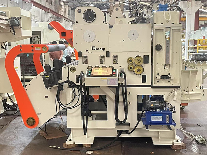
The line runs 2.5 mm by 1,250 mm hot-rolled pickled strip through a seven-roll machine at 90 strokes a minute, three shifts, eight-tonne coils.
Coil ends are joined on the floor with a MIG welder so the line does not stop for a coil change. The bead is dressed with a grinder when the operator has time, which on a three-shift line means not always.
Six weeks in, the customer's press operator started rejecting panels for surface marks. The marks were faint transverse bands, evenly spaced, on the top face only.
Their maintenance team measured the spacing: 220 mm. Nobody connected that number to anything, and the first response was to reduce roll penetration by 0.1 mm.
That is the standard first move, and it cost them a week of flatness compliance while the marks continued.
What the Roll Surface Showed
Two measurements settled it, and neither needed the machine to be stripped.
Runout. A dial indicator on roll four, in situ, showed 0.08 mm of total indicator reading at one point on the circumference, against less than 0.01 mm everywhere else.
Hardness. A portable Leeb tester gave 52 HRC at that same spot, against 60 HRC on the rest of the roll body.
A soft, flattened spot on a hardened roll is a bruise, not wear. Wear removes material evenly and slowly; a bruise is a local plastic deformation that leaves a raised shoulder around a depression.
Once the roll was out, the cause of the 220 mm spacing was obvious. A 70 mm work roll has a circumference of 220 mm, so the mark was one roll revolution, printed by one point on one roll.
That arithmetic is worth remembering, because it separates a roll defect from a die problem in under a minute. Marks at feed pitch come from downstream. Marks at roll circumference come from the roll.
Why a 1.6 mm Weld Bruises a 70 mm Roll
The weld bead stood about 1.6 mm proud of the strip. At the weld, effective thickness was 4.1 mm instead of 2.5 mm, a 64% step passing through a gap set for the nominal gauge.
The roll has nowhere to go, so the gap opens. The separating force goes into the roll necks, the bearing housings and the adjusting screws, and the load is applied over a contact patch only as wide as the bead.
Contact area that small turns a modest separating force into a contact stress several times the normal rolling load.
On a 60 HRC surface, a local stress above the shakedown limit yields the surface on the first pass and work-hardens the shoulder around it.
The result is a shallow dent with a raised rim, 0.08 mm deep in this case. From then on, every revolution of that roll prints the rim onto the strip.
Two more details made it worse. The shop was welding without a backing strip, so the root side had a second, softer bead. And the weld was harder than the parent metal, so the roll took the entire deformation.
Tell a Weld Bruise From a Wear Mark
Surface marks have distinct signatures, and the signature tells you which subsystem to open. Guessing wrong costs more than the repair.
| What you see | What it means | How to confirm | Where the guess costs you |
|---|---|---|---|
| Faint transverse bands repeating at roll circumference, one face only | Localised roll damage: a bruise or embedded debris on one roll | Dial indicator on each roll in situ, looking for 0.05 to 0.1 mm of runout at one point | Re-grinding the wrong roll costs a day of downtime and leaves the mark exactly where it was |
| Bands that appear in bursts, then fade for hundreds of metres | An event passing through the machine, typically a weld or a hard spot in the coil | Log strip length when the marks appear and compare against the weld positions on the coil ticket | Blaming penetration means you lose flatness compliance and still ship marked panels |
| Marks scattered across both faces, no periodicity | Penetration or roll gap too tight for the material | Reduce penetration in 0.05 mm steps and re-run two metres | Costs flatness margin. It is a real cause, but only when the marks have no spacing pattern |
| Marks concentrated at both strip edges | Edge damage from coil handling, or a guide contacting the strip | Inspect the coil edges and the entry guide, then check the roll edge gaps | A guide change that does not fix the marks, plus a week of chasing the wrong component |
| Marks present from the first metre of a fresh coil | Incoming coil surface damage, often from crane clamps or stacked storage | Inspect the outer wrap before loading and photograph the coil as received | A maintenance visit to the machine that finds nothing, and a supplier argument you cannot win without evidence |
In this case the first row was correct, and the weld evidence came from the second row. Both were true at once, which is why the diagnosis took a week rather than an hour.
Where a Straightener Feeder Should Not Take a Weld
Running welds is a legitimate practice, but there are four situations where the arithmetic stops working and no amount of care rescues it.
Small rolls with short necks. Neck deflection under the weld load can exceed the bearing clearance, and the load then goes into the bearing rather than the strip.
On a machine with 70 mm rolls, the weld load is already near the practical ceiling.
Coated or pre-painted material. A weld bead will mark the roll, and a marked roll then prints on the next fifty coils of coated strip. If a machine runs both bare and coated material, welds do not belong on it.
Lines holding tight feed accuracy. The thickness step disturbs the feed roll grip for two or three pitches.
A line holding ±0.05 mm on bare strip will not hold it across a weld, so plan on scrapping the parts around the joint.
A weld near the coil end. Inside the last three metres the peeler and the hold-down have little control, and the weld whips the strip. That is a handling problem the machine cannot solve.
A lap weld doubles the step of a butt weld, and on a heavy-gauge line it should be treated as a defect rather than a joint.
Four questions come up every time a shop decides whether to keep welding.
How much does a 1.5 mm weld bead add to strip thickness?
On 2.5 mm strip it takes the section from 2.5 mm to about 4.1 mm, a 64% step. Every roll in the machine sees that step as an impact, not a rolling load.
How much roll life does dressing the weld buy: 6 weeks or 14 months?
In this case, grinding the bead to within 0.3 mm of the parent metal plus slowing the line through the weld took roll life from six weeks to fourteen months.
The weld itself did not change. Only the step height and the entry speed did.
How deep a bruise shows up as a visible mark, 0.05 mm or 0.2 mm?
A 0.05 mm local deformation is enough to print a visible mark on 2.5 mm pickled strip. This roll measured 0.08 mm, which is well inside what a dial indicator will find in situ.
How far either side of a weld should the line slow down?
Three metres either side, at 30 to 40% of line speed. The impact load scales with entry speed, so halving the speed roughly halves the peak force on the roll.
What to Change If You Must Run Welded Coils
The shop kept welding, because stopping the line twice a shift cost more than the roll damage. What changed was how the weld is made and how the machine sees it.
| Change | What it buys | What it costs you |
|---|---|---|
| Dress the bead flush to within 0.3 mm | Cuts the thickness step by roughly 80%, which removes most of the impact load | Three to five minutes of operator time per weld, and a grinder kept at the line |
| Slow the line through the weld | Halves the peak force on the roll at 40% line speed | Two to four minutes of lost production per coil, plus a control change if there is no weld input |
| Open the roll gap 0.2 mm for the weld pass | Protects the roll surface at the cost of flatness over that length | The scrap length around the joint, and an operator who has to remember to reset the gap |
| Fit a weld detector wired to the line speed | Makes the slowdown automatic instead of dependent on memory | Capital and integration time, and a sensor that has to survive the line environment |
| Move to a shear-and-weld unit with a planisher | Step under 0.15 mm with a consistent joint, no grinding | The largest capital item on this list, and a new maintenance discipline |
| Run coil to coil without welding | Removes the problem entirely | Floor space for a second pay-off, and a coil change the line has to survive |
The first three rows are what most shops actually implement, because they cost time rather than capital. The fourth row is what makes them reliable.
One detail matters more than the table suggests: the dress height. Operators under time pressure grind until the bead looks flat, which leaves 0.5 to 0.8 mm proud.
A go/no-go gauge held against the joint removes the judgement call.
- Write the joint tolerance down. A number on the shop wall — bead height within 0.3 mm of the parent metal — turns a habit into a specification an auditor can check.
- Give the operator a gauge, not a rule. A hardened go/no-go block takes two seconds and cannot be argued with at the end of a night shift.
- Scrap the section behind the weld. Two metres either side carries the thickness disturbance and the flatness error, and no downstream setting recovers it.
- Log the welds on the coil ticket. When a mark appears, the log tells you within a minute whether it followed a joint. Without it, the diagnosis starts from zero every time.
- Record roll runout after every re-grind. A baseline measurement for each roll makes the next bruise obvious before the customer finds it.
What the Fix Cost and What It Bought
The roll was re-ground, which returned 0.06 mm of material and cost a day of production.
The dressing procedure, the go/no-go gauge and the automatic slowdown were introduced over the following fortnight. Roll four has not been re-ground since, and the marks have not returned.
The measurable outcome was a scrap rate on marked panels that fell from just over 4% to under half a percent, and a roll maintenance interval that moved from six weeks to over a year.
None of that came from a better machine. It came from treating the coil joint as a process step with a tolerance instead of an inconvenience to be hurried through.
Twelve years of building these lines has produced the same conclusion repeatedly: the failures that look like machine faults are usually upstream process steps that nobody wrote a number for.
Where to go next
A bruised roll is one way incoming material damages the line. The roll geometry, penetration and defect-to-correction logic that keeps a straightener within flatness spec are set out in the guide library.
the complete 3-in-1 decoiler straightener feeder guide