How Does Coil Feeding Change a Progressive Die Design?
- Share
- publisher
- David Park - Senior Stamping Engineer, FANTY Machinery
- Issue Time
- Sep 20,2026
Summary
A Tier-2 appliance stamper moved a four-station progressive die from hand-stacked blanks to coil feeding, and the die stopped working. This is the redesign sequence that fixed it, the six die features that had to change, the speed the conversion costs, and the cases where coil feeding is the wrong answer.
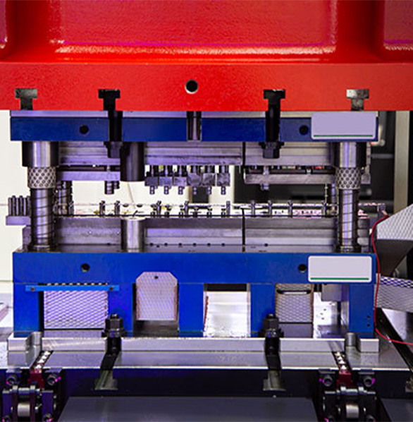
A Tier-2 appliance stamper in northern Italy ran a 200-tonne press with a four-station progressive die for a bracket, fed from pre-cut blanks stacked by hand.
Two operators kept the stack full, and the line produced 1.9 million parts a year.
When they moved to coil feeding, the die did not work. Not because the press changed, and not because the feeder was badly set.
The die had been designed for the way blanks arrive, and strip arrives differently — continuously, at a tolerance, on a pass line, with a skeleton that has to go somewhere.
This is what actually changed on that die, in the order the changes had to be made.
If you are weighing the same conversion, the die work is the part that decides whether the project pays, and the ordering logic sits alongside the wider material in our coil line knowledge base.
What Changes on the Shop Floor
The first surprise is that the part did not change. Same bracket, same 1.2 mm SPCC, same 250 mm strip width, same 180 mm feed pitch, same two-out layout.
What changed was everything the die assumes about how material is presented.
Blanks arrive one at a time, positioned by the operator, with sheared edges that are straight within a millimetre.
Strip arrives as a continuous 250 mm ribbon with a width tolerance of ±0.5 mm, a camber of a few millimetres over a 2-tonne coil, and a coil set that has to be taken out upstream.
The old die also had no concept of feed timing. Blanks were placed while the ram was up.
Strip has to be advanced by an NC servo feeder during a defined window, and the die has to be out of the way while that happens. The machine range is listed in our product range.
That single requirement — the die must let go of the strip during feed — drives most of the redesign. Everything below follows from it.
Three Die Decisions That Move First
On the Italian job, the redesign sequence was fixed by the geometry rather than by preference. Changing these three in any other order means re-machining work you have already done.
Pass line and shoe height. The feeder sets a strip pass line, typically 900–1,100 mm above the floor depending on machine size.
The die has to accept the strip at that height, and the tolerance is tight: a mismatch of 0.3 mm tilts the strip and shows up as a feed-length error at the far end of the coil.
Pilot release and lifter travel. Fixed pilots that located a stationary blank now have to release the strip before the feed starts and re-engage after it stops.
That means spring-loaded or cam-driven pilots with lifters that raise the strip clear of the pilot tips.
Strip guidance at entry. Blanks were guided by the operator. Strip needs a positive entry guide with edge rollers, plus enough clearance to absorb camber without pinching the strip or letting it wander off-centre.
On this die the pass line change came first, because it determined whether the shoe had to be re-machined or replaced.
It had to be re-machined — 6 mm off the bottom, then re-shimmed — and that was three days of downtime booked before anything else could be measured.
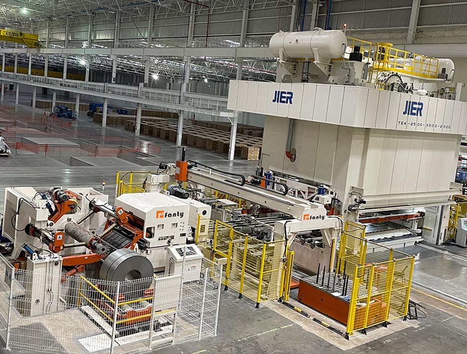
The Die Features That Have to Be Redesigned
Six features carry the whole conversion. The middle column is what the die was doing before; the right column is where each change extracts its price.
| Die feature | Blank-fed baseline | What coil feeding demands | Where it costs you |
|---|---|---|---|
| Pass line and shoe height | Set by the blank loader; anything within ±2 mm worked | Strip must meet the feeder pass line within about ±0.1 mm | Shoe re-machining or replacement, plus booked downtime before any measurement is possible |
| Pilot release | Fixed pilots, no release needed | Spring or cam release with lifter travel of 3–5 mm above strip surface | Costs 10–20% of strokes. The press may be rated 200 SPM, but the die now runs at 170 |
| Strip entry guidance | Operator positioned the blank | Positive entry guide with edge rollers and camber clearance | Extra setup step on every die change, and a guide that has to be adjusted for each strip width |
| Skeleton and scrap | One skeleton per blank, easy to clear | Continuous skeleton needs a chopper or an inclined chute with clearance for 180 mm pitch | Floor space, a second maintenance item, and a jam point that stops the line |
| Slug control | Slugs fell into a tray | Counter-bored or inverted slug removal, vacuum assist on small holes | Tooling cost and die height. Vacuum lines add a failure mode that shows up as slug pulling |
| Die protection sensors | Part-out detection was optional | Strip-present, buckle, misfeed and tail-out sensing wired into the press control | Wiring and commissioning time, plus false trips until the thresholds are tuned |
Read the pilot-release row twice. It is the row that most often decides whether the conversion is worth doing, because it is the only change that permanently reduces output.
On the Italian die, pilot release dropped the running speed from 200 SPM to 172 SPM. That is a 14% capacity loss on the press, offset by the removal of two operators and the elimination of blank stacking.
At the volumes involved it paid in eleven months. At half those volumes it would not have.
Where This Conversion Fails
Coil feeding is not a universal upgrade. Five situations where converting a blank-fed die will cost more than it saves, or where the numbers used to justify it are misleading.
Thick, short-run parts. Above roughly 6 mm, the coil itself becomes the handling problem.
Straightening 6 mm HSLA needs a heavier machine than the parts justify, and a 2-tonne coil of 6 mm strip is difficult to load safely.
Frequent material changes. If the die runs four grades in a shift, each change means a coil change, a threading cycle and a straightener reset. Blank feeding lets you switch grades by switching stacks.
Parts wider than available coil. Coil width availability is not infinite. If your part needs 1,500 mm of strip, you may be limited to a narrow supplier base and longer lead times than blanks would carry.
Surface-critical parts. Coil handling marks strip: uncoiling, straightening and feeding all touch both faces. If the part is visible after painting, count the cost of rejected surface before you count the savings.
The material-yield claim. The standard justification is "coil feeding saves 8% material". That figure comes from nested layouts where blanks leave offal between parts.
If your blank layout was already tight, the real saving is closer to 2–3%, and the pilot-release speed loss can erase it.
The last point deserves emphasis, because it is where conversions get approved on a spreadsheet that nobody re-checks afterwards. Material yield improvement and speed loss move in opposite directions.
Model both before you commit.
Six Checks Before You Commit the Die
- Measure the pass line the feeder will actually run at. Not the catalogue figure — the measured height with the machine installed and levelled. A 0.3 mm error at the feeder becomes a feed-length error at the far end of the coil.
- Calculate the speed loss before you approve the project. Model pilot release, lifter travel and strip settle time together. If the die drops from 200 to 170 SPM, that is the number the payback has to absorb.
- Check skeleton clearance at the tightest station. The continuous skeleton has to pass every station without catching. On a four-station die with a 180 mm pitch, that is often the constraint, not the part.
- Verify camber against your guide clearance. Coil camber of 3 mm over a coil length will find any under-sized entry guide. Measure the camber on a real coil, not a sample.
- Plan the tail-out. The last 2 m of every coil is where misfeeds happen. Decide now whether you scrap it, slow down for it, or fit tail-out sensing. Deciding later means a scrap bin full of mangled parts.
- Confirm the die can still run on blanks. Keeping blank-feeding capability costs very little and gives you a fallback for short runs. Once the shoe is machined for one pass line, going back is expensive.
Can a coil-fed die absorb 0.5 mm of strip width variation?
Slit coil typically arrives within ±0.5 mm of nominal on a 250 mm width, and mill edge condition varies more than the width does.
Size the entry guide for nominal width plus 1 mm total clearance, then use spring-loaded edge rollers rather than fixed guides so the strip is centred without being pinched.
How many strokes does pilot release cost on a 200 SPM press?
On a 200 SPM press running a 180 mm pitch, expect 10–20%. The Italian die settled at 172 SPM, a 14% loss.
The loss scales with feed length: a longer feed needs a longer release window, so a 400 mm pitch can cost more than 20%.
Does a die conversion pay back at 1 million parts a year?
On a two-operator blank-fed line, the conversion paid back in eleven months at 1.9 million parts a year.
Halve the volume and the payback stretches past three years, at which point buying a new die designed for coil from the start is usually the better decision.
Can one die run both blanks and coil?
Yes, if you design for it from the beginning — a shimmed shoe with two pass-line positions and pilots that work in both modes.
Retrofitting that flexibility later costs more than the original die, so decide before the shoe is machined.
Does coil feeding add 10% to the press tonnage I need?
Not for the forming work, but it changes how the load is distributed.
A coil-fed die with pilots and lifters working against strip tension can need 5–10% more tonnage at the first station than the same die fed from blanks, because the strip is being pulled rather than sitting free.
Check the tonnage curve before you assume the press is adequate.
What die height change does coil feeding force at a 1,000 mm shut height?
It depends on the feeder. A typical NC servo feeder sets a pass line 900–1,100 mm above the floor, which is often 40–80 mm higher than a blank loader.
If the press shut height cannot absorb that, the die shoe has to be machined or the press bed raised.
Converting or Buying New: The Break-Even Line
Conversion and replacement are not competing philosophies. They split cleanly on how much of the die has to move.
If only the shoe and the pilots change, convert. The tooling cost stays in the low four figures and the die keeps its proven stations.
If the skeleton path, slug control and sensor layout all have to be rebuilt, you are paying for most of a new die while keeping the compromises of the old one.
At that point a die designed for coil from the first station usually wins on both speed and maintenance.
The dividing line on the Italian job was the skeleton. Two stations had to be re-laid to clear a continuous skeleton, and that pushed the conversion cost to within 20% of a new die.
They converted anyway, because a new die would have needed a re-validation the customer would not fund. Another shop with a different customer would reasonably have chosen the opposite.
FANTY has supplied coil-feeding equipment for 12 years, with more than 200 lines installed.
The die-side questions above are the ones that decide whether a line performs, and they are worth settling before a feeder is ordered rather than after.
Where to go next
Die design follows what the feeding system can hold. Where the feed error is generated between the coil and the die is set out in the guide library.
the coil line guide library